The post Memory Bandwidth vs Latency: How RAM Affects Real-World Performance appeared first on .
]]>Memory performance is often described using data rates and latency timings. While both affect how a system accesses data, they measure different aspects of memory behavior. A memory module can offer high bandwidth but still have relatively high access latency, or provide low latency without delivering the highest possible throughput.
Understanding this distinction helps explain why two memory configurations with similar specifications can behave differently in real-world applications. It also provides a more accurate way to evaluate RAM upgrades than comparing frequency or CAS latency alone.
1. What Is Memory Bandwidth?
Memory bandwidth describes how much data can be transferred between system memory and the memory controller over a given period. It is commonly expressed in gigabytes per second (GB/s).
For DDR memory, the advertised data rate is measured in transfers per second rather than the physical clock frequency. For example, DDR5-6000 supports a nominal data rate of 6,000 million transfers per second per data pin.
For a standard 64-bit memory channel, the theoretical peak bandwidth can be calculated as:
Theoretical bandwidth = Data rate × Bus width ÷ 8
For DDR5-6000:
6,000 MT/s × 64 bits ÷ 8 = 48,000 MB/s, or 48 GB/s
This is the theoretical peak bandwidth for one 64-bit data path, before accounting for protocol overhead, refresh activity, access patterns and other factors. Actual application performance will vary.
A higher data rate increases the amount of data that can potentially be transferred each second. Increasing the number of active memory channels can also increase aggregate bandwidth, provided the platform supports the configuration.
Bandwidth is particularly important when applications need to move large amounts of data continuously. Examples include integrated graphics, scientific computing, large-scale image processing, video workloads and applications that process large datasets.
However, bandwidth alone does not determine how quickly a processor can obtain a specific piece of data.
2. What Is Memory Latency?
Memory latency describes the delay involved in accessing data. In practical terms, it helps explain how long a processor may need to wait for a memory operation to complete.
One commonly discussed timing is CAS latency (CL), which represents the number of memory clock cycles between a read command and the availability of the requested data under the relevant conditions.
Because CL is expressed in clock cycles, it cannot be compared accurately without considering the memory clock period.
For DDR memory, the approximate CAS latency in nanoseconds can be calculated as:
CAS latency (ns) = CL × 2,000 ÷ Data rate (MT/s)
For example, consider two configurations:
| Memory configuration | Data rate | CAS latency | Approximate CAS latency |
|---|---|---|---|
| DDR4-3200 CL16 | 3,200 MT/s | 16 cycles | 10 ns |
| DDR5-6000 CL30 | 6,000 MT/s | 30 cycles | 10 ns |
Although the DDR5 configuration has a higher data rate, its CL value is also higher. The approximate CAS latency of both configurations is 10 ns.
This illustrates an important point: a higher CL number does not automatically mean higher latency in nanoseconds.
However, CAS latency is only one component of memory access timing. Actual memory access latency also depends on factors such as row activation, precharge operations, memory-controller scheduling, command timing, queueing and the processor’s memory architecture.
Consequently, CAS latency should not be treated as a complete measurement of end-to-end memory latency.
3. Bandwidth vs Latency: The Key Differences
Bandwidth and latency describe different performance characteristics.
| Characteristic | Memory bandwidth | Memory latency |
|---|---|---|
| What it measures | Amount of data transferred per unit of time | Delay associated with accessing data |
| Common units | GB/s | Nanoseconds (ns), or clock cycles for individual timings |
| What higher performance means | More data can be transferred per second | Less time is required to access data |
| Commonly influenced by | Data rate, channel configuration, bus width and workload | Memory timings, data rate, controller behavior and access patterns |
| Particularly relevant to | Large, sustained data transfers | Latency-sensitive and dependency-heavy operations |
| Typical evaluation methods | Memory bandwidth benchmarks | Memory latency benchmarks |
Neither metric is universally more important than the other.
A workload that transfers large blocks of data may benefit significantly from higher bandwidth. Another workload that repeatedly waits for individual memory accesses may be more sensitive to latency.
Many applications depend on both.
4. How Memory Bandwidth Affects Real-World Performance
Higher memory bandwidth can improve performance when memory throughput is a limiting factor.
Integrated Graphics
Integrated GPUs typically share system memory with the CPU. Graphics workloads may need to transfer large amounts of texture, geometry and rendering data through the available memory subsystem.
When bandwidth is a bottleneck, a higher data rate or a suitable multi-channel memory configuration can improve graphics performance.
The actual benefit depends on the integrated GPU, memory architecture, workload and other system limitations. Increasing bandwidth will not necessarily produce a large improvement if performance is limited elsewhere.
Video Editing and Data Processing
Some video processing tasks, image operations and data-processing applications move large volumes of information through memory.
In these scenarios, additional bandwidth can help reduce transfer-related limitations, particularly when the workload can take advantage of parallel memory operations.
However, performance may still depend more heavily on CPU processing capacity, GPU acceleration, storage throughput or software optimization.
Multitasking and Memory-Intensive Applications
Running several demanding applications simultaneously can increase aggregate memory traffic.
More available bandwidth may help the system serve concurrent requests, but bandwidth does not replace memory capacity. If RAM is insufficient and the operating system frequently moves data between RAM and storage, adding capacity may provide a greater improvement than increasing the memory data rate.
5. How Memory Latency Affects Real-World Performance
Latency becomes particularly relevant when a processor cannot proceed until a requested piece of data arrives.
Gaming
Games frequently involve many small data accesses associated with game logic, object updates, simulation and other CPU-side tasks.
Some games are sensitive to memory latency, especially when the CPU is the performance bottleneck. Lower effective memory latency may improve frame times or reduce certain performance inconsistencies.
However, gaming performance also depends on CPU architecture, cache behavior, GPU, game engine, resolution and graphics settings. There is no universal latency improvement that guarantees a specific increase in frames per second.
Database and Transaction Processing
Some database operations and transaction-heavy workloads rely on frequent, dependent memory accesses. When an operation must wait for data before the next step can continue, latency can become a significant factor.
The benefit of lower memory latency depends on the application’s access patterns, caching behavior, storage subsystem and degree of parallelism.
General System Responsiveness
Memory latency can influence how quickly certain operations receive the data they need. Nevertheless, everyday responsiveness is affected by many components, including CPU performance, operating-system scheduling, application design, storage activity and background processes.
A lower CAS latency value alone does not guarantee that a computer will feel noticeably faster.
6. Why Memory Frequency and CAS Latency Must Be Evaluated Together
Memory data rate and CAS latency are often discussed separately, but evaluating them together provides a more useful starting point.
Consider these hypothetical configurations:
| Configuration | Data rate | CAS latency | Approximate CAS latency |
|---|---|---|---|
| A | 5,600 MT/s | CL28 | 10 ns |
| B | 6,000 MT/s | CL30 | 10 ns |
| C | 6,400 MT/s | CL32 | 10 ns |
All three configurations have an approximate CAS latency of 10 ns, despite having different data rates and CL values.
Their theoretical peak bandwidth per 64-bit data path differs:
| Configuration | Theoretical peak bandwidth |
|---|---|
| DDR5-5600 | 44.8 GB/s |
| DDR5-6000 | 48.0 GB/s |
| DDR5-6400 | 51.2 GB/s |
These examples show how higher data rates can increase theoretical bandwidth even when approximate CAS latency remains similar.
They do not mean that the three configurations will perform identically in every application. Other timings, memory-controller behavior, platform limits and stability considerations can produce different results.
They also illustrate why selecting RAM based only on its advertised frequency or CL value can lead to incomplete conclusions.
7. Memory Channels and System Architecture Matter Too
Memory bandwidth is influenced not only by the data rate of individual modules but also by the memory channels available to the processor.
A system with more active memory channels may offer greater aggregate bandwidth than a system using fewer channels, assuming the platform and installed configuration support those channels.
However, desktop motherboard slot labels can be confusing. Installing two DIMMs does not necessarily mean that the system has two independent memory channels, and the number of DIMM slots is not the same as the number of memory channels.
Memory channel configuration must be evaluated according to the CPU’s memory controller and motherboard design.
Memory rank, DIMM organization and controller scheduling can also affect how efficiently memory requests are handled. Some configurations allow the controller to interleave operations, improving utilization under suitable workloads. The benefit depends on the platform and application rather than the number of ranks alone.
For this reason, memory performance should be assessed as part of the complete memory subsystem, not simply as an isolated module specification.
8. How to Evaluate Memory Performance More Accurately
A meaningful comparison requires more than reading the specifications printed on a RAM module.
Step 1: Check the Platform
Confirm the CPU’s supported memory data rates, motherboard compatibility and available channel configuration. A module’s advertised data rate may depend on enabling an overclocked memory profile, such as XMP or EXPO, and may not be the system’s default operating rate.
Step 2: Review Capacity and Configuration
Before pursuing higher bandwidth or lower latency, confirm that the system has sufficient memory capacity for its workload.
If memory pressure causes frequent paging, increasing RAM capacity may provide a much greater improvement than changing timings.
Step 3: Compare Complete Specifications
Review the data rate, primary timings, relevant secondary timings, channel configuration and operating stability.
A single CL value cannot represent all memory timings, while a data rate alone cannot show the full latency characteristics of the system.
Step 4: Use Workload-Relevant Benchmarks
Synthetic memory benchmarks can help measure theoretical or practical bandwidth and access latency. Application benchmarks are needed to determine whether those differences translate into meaningful improvements for the actual workload.
Whenever possible, compare configurations under the same CPU settings, software version, operating conditions and workload.
Step 5: Verify Stability
A configuration that produces a high benchmark score but experiences memory errors or instability is not a successful upgrade.
Memory settings should be validated through appropriate stability testing, particularly when changing data rates, timings or memory profiles.
9. Choosing Memory Solutions for Different Applications
The relationship between bandwidth and latency is important not only for individual PC users but also for businesses selecting memory modules for specific platforms and applications.
Gaming systems may prioritize a balance of data rate, timings and compatibility. Workstations processing large datasets may benefit from greater memory bandwidth, while other workloads may be more sensitive to access latency or memory capacity.
For system builders, distributors and OEM customers, evaluating RAM requires more than comparing the advertised data rate and CAS latency. Platform compatibility, module configuration, operating stability and consistent product specifications also matter.
A suitable memory solution should meet the requirements of the intended platform and workload rather than rely on one specification as a universal performance indicator.
10. Oreton: A Shenzhen-Based DRAM and SSD Manufacturer
As a Shenzhen-based SSD and DRAM manufacturer in China, Oreton provides memory and storage solutions for distributors, system integrators and OEM/ODM customers.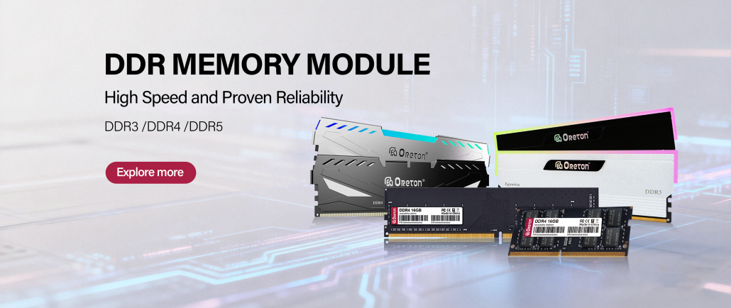
Our memory portfolio includes DDR4 and DDR5 modules for a range of computing applications. When evaluating memory solutions, we recognize that data rate and latency are only part of the overall specification. Compatibility, module configuration, operating stability and product consistency are also important considerations.
Oreton focuses on practical product requirements, manufacturing quality control and consistent supply to support customers sourcing memory and storage products for their markets and projects.
For businesses seeking a DRAM manufacturer, memory module supplier or SSD and DRAM OEM/ODM partner in Shenzhen, China, Oreton offers a product portfolio designed to support different platform and application requirements.
Explore our memory and storage solutions to learn more about Oreton and our product range.
Oreton — Your One-stop Storage Solutions.
Conclusion
Memory bandwidth and latency describe two different aspects of RAM performance. Bandwidth determines how much data can be transferred over time, while latency describes the delay associated with accessing data.
Higher bandwidth can benefit data-intensive workloads, while lower latency can help applications that depend on timely memory access. Many real-world workloads rely on both, and their sensitivity varies with CPU architecture, memory configuration and software behavior.
A balanced evaluation considers data rate, timings, capacity, channel configuration, platform compatibility and workload-specific results. Rather than assuming that the highest frequency or lowest CL value is always best, compare the complete memory configuration and verify its impact under realistic conditions.
For businesses sourcing memory modules, these technical factors should be considered alongside product consistency, compatibility requirements and supplier capabilities. Working with a manufacturer that understands both memory specifications and application requirements can help support more informed product selection and long-term supply planning.
The post Memory Bandwidth vs Latency: How RAM Affects Real-World Performance appeared first on .
]]>The post SSD SMART Attributes: Which Drive Health Indicators Matter? appeared first on .
]]>An SSD can continue to operate normally while its internal health indicators change over time. Conversely, a drive may experience unexpected problems even when its reported health status appears acceptable. Understanding Self-Monitoring, Analysis and Reporting Technology (SMART) data helps users evaluate storage conditions, identify potential warning signs, and make more informed maintenance decisions.
However, SMART is not a universal pass-or-fail test. Different SSD controllers, firmware implementations, and monitoring tools may report different attributes or interpret them differently. To assess drive health accurately, it is important to understand what each indicator measures, what it can reveal, and where its limitations lie.
1. What Is SSD SMART?
SMART is a monitoring and reporting system that allows a storage device to expose information about its operating history, usage, error conditions, and, where supported, estimated health.
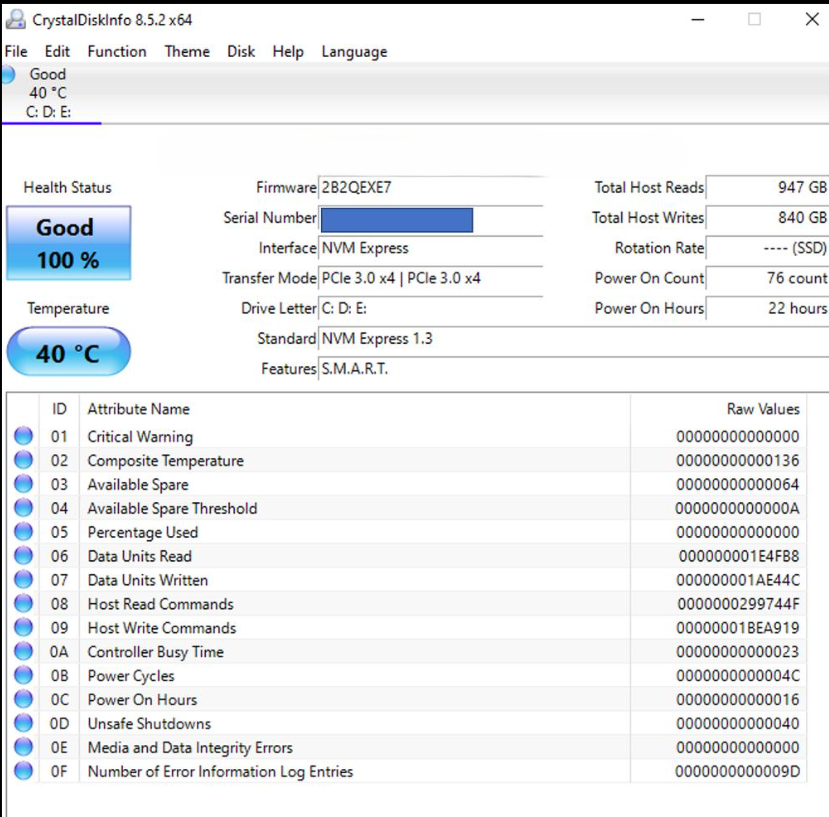
For SSDs, SMART data may include:
- Power-on hours and power-cycle counts
- Total host reads and writes
- NAND wear indicators and estimated remaining life
- Temperature readings
- Media and data integrity errors
- Error logs and interface-related issues
- Available spare capacity and threshold warnings
The exact attributes depend on the drive and its firmware. SATA SSDs commonly expose SMART attributes through ATA commands, while NVMe SSDs provide standardized health information through their SMART / Health Information log. Some underlying measurements are comparable, but their definitions and reporting formats are not always identical.
SMART data is most useful when interpreted as a collection of indicators over time rather than as a single health percentage.
2. Power-On Hours and Power-Cycle Count
Power-on hours indicate how long a drive has been powered on, while the power-cycle count records how many times it has been powered up. These values provide context for understanding the drive’s operating history.
A drive with a high number of power-on hours is not necessarily unhealthy. SSDs are designed to operate over extended periods, and total powered-on time alone does not establish how much NAND wear has occurred.
Likewise, frequent power cycles do not automatically indicate a fault. They may simply reflect normal usage patterns, such as a desktop computer being switched on and off daily.
These indicators become more useful when considered alongside workload, write volume, temperature history, and error records. For example, a drive with relatively low power-on hours but substantial host writes may have experienced a much heavier workload than its operating time suggests.
What to look for: Unexpected changes, unusual operating history, or values that do not match the device’s known usage. Neither power-on hours nor power-cycle count should be used alone to determine remaining SSD lifespan.
3. Total Host Writes and NAND Wear
Total host writes measure the amount of data written to the drive by the host system. This is one of the most useful indicators for understanding SSD workload and endurance consumption.
However, host writes and NAND writes are not the same measurement. The SSD controller may write additional data internally during garbage collection, data relocation, and other flash-management operations. The relationship between host writes and NAND writes is commonly described using write amplification.
For example, a workload involving frequent small random writes may generate more internal NAND activity than a workload consisting mainly of large sequential writes, even when the host reports a similar amount of data written.
To understand endurance, it is useful to distinguish three concepts:
- Host writes: Data written by the operating system or applications to the SSD.
- NAND writes: Data actually programmed into NAND flash, including internal controller activity where measurable.
- Rated endurance: The manufacturer’s specified endurance rating, often expressed as total bytes written (TBW) or another defined endurance measure.
A drive approaching its rated host-write endurance is not necessarily about to fail. Endurance ratings are defined under particular test conditions and do not predict the exact failure time of an individual drive.
For NVMe SSDs, the SMART / Health Information log includes a Data Units Written counter. Its reported value represents host data units written, not a direct measurement of physical NAND writes. Other attributes, such as Percentage Used, provide additional endurance-related information.
What to look for: Compare cumulative host writes with the drive’s specified endurance rating, review the workload, and observe how wear-related indicators change over time.
4. Percentage Used and Available Spare
NVMe SSDs provide two especially useful health fields: Percentage Used and Available Spare.
Percentage Used
Percentage Used is an estimate of the percentage of the drive’s rated endurance that has been consumed. A reported value of 20% generally indicates that approximately one-fifth of the rated endurance has been used according to the drive’s estimation method.
A value of 100% means the estimated rated endurance has been consumed. It does not necessarily mean that the drive has failed or can no longer store data. The device may continue to operate beyond this point, although its remaining endurance should be evaluated carefully.
Values above 100% may also be reported, depending on the device and specification implementation.
Available Spare
Available Spare represents the remaining spare capacity available to the controller, expressed as a percentage. Spare blocks help the SSD manage unusable or worn-out flash blocks and maintain normal operation.
NVMe also defines an Available Spare Threshold. If the available spare value falls below the specified threshold, the drive can report a health warning.
These fields are not interchangeable. Percentage Used estimates endurance consumption, while Available Spare reflects a different aspect of the drive’s operational reserve.
What to look for: Review both fields, check the manufacturer’s specifications, and pay attention to threshold warnings instead of relying on a generic health score alone.
5. Temperature: An Important Operating Indicator
SSD temperature affects operating conditions and can influence sustained performance. Under heavy workloads, particularly during long transfers or sustained random I/O, an SSD may become warm enough to activate thermal management or throttling.
SMART temperature readings help users determine whether the drive is operating within its specified range. Depending on the device, a monitoring tool may display a composite temperature, a controller temperature, or additional sensor readings.
A brief temperature increase during a demanding workload is not automatically a problem. More important factors include how long the drive remains hot, whether the temperature exceeds the manufacturer’s operating limits, and whether performance changes at the same time.
Temperature limits vary by model. There is no single universal threshold that applies to every SATA or NVMe SSD.
What to look for: Compare readings with the specific drive’s operating-temperature specifications. If high temperatures coincide with declining sustained performance, investigate airflow, heatsink installation, thermal-pad contact, and the surrounding system environment.
6. Media Errors and Data Integrity Errors
Error-related SMART indicators can provide important evidence about storage reliability, but their meaning depends on the interface and attribute definition.
NVMe SSDs expose fields including Media and Data Integrity Errors and Error Information Log Entries.
Media and Data Integrity Errors count detected errors associated with unrecovered data integrity problems or media-related issues, as defined by the NVMe specification. A nonzero value deserves investigation, especially if it continues to increase.
Error Information Log Entries counts entries recorded in the NVMe error information log. This is not equivalent to a count of unrecoverable media failures. Some entries may relate to commands, invalid parameters, or other conditions, so the underlying log details matter.
SATA SMART attributes may expose different counters, such as reported uncorrectable errors, reallocated sectors, or other vendor-defined records. Their exact meanings should be confirmed against the drive documentation.
A single historical error does not always indicate an ongoing fault. The key questions are whether the error is persistent, whether the counter is increasing, and whether the system also reports I/O errors, corrupted data, or unexpected disconnections.
What to look for: Investigate repeated or increasing media and integrity errors, review available error logs, and back up important data if reliability is in doubt.
7. Unsafe Shutdowns and Interface Errors
Some SMART reports include unsafe shutdown counts, command timeouts, CRC errors, or other interface-related indicators. These can help distinguish potential storage-media problems from issues involving power delivery, cabling, connections, or the host system.
For NVMe drives, Unsafe Shutdowns records occasions when the controller detects that power was removed without a shutdown notification. A high count may reflect power outages, forced shutdowns, system crashes, or other interruptions. It does not, by itself, prove that the SSD is damaged.
For SATA drives, CRC-related errors may point toward data-transfer problems along the interface path. Depending on the system, checking the SATA cable, connector, and port may be more relevant than replacing the SSD immediately.
Interpret these records alongside system logs and the circumstances in which the errors occurred.
What to look for: Repeated unexpected shutdowns, increasing interface errors, or storage disconnects that coincide with system instability.
8. How to Read SMART Data Correctly
A reliable assessment starts with the correct tool and the correct attribute definitions.
Step 1: Identify the Drive and Interface
Confirm the SSD model, firmware version, and whether it uses SATA or NVMe. This determines which health fields are available and how they should be interpreted.
Step 2: Use a Compatible Monitoring Tool
Use a reputable monitoring utility that supports the drive and its interface. Tools may display raw values, normalized values, estimated health percentages, or simplified warnings.
A simplified health score is useful for quick reference, but it may hide differences between wear, error history, and temperature. For NVMe drives, checking the underlying SMART / Health Information log can provide more context.
Step 3: Check Multiple Indicators
Avoid making a judgment based on one field. Review endurance consumption, available spare capacity where applicable, temperature, media errors, and other relevant records together.
Step 4: Track Changes Over Time
A snapshot shows the current reported state; a trend can reveal whether the situation is stable or deteriorating. Record readings periodically and compare them under similar workloads when possible.
Step 5: Back Up Data When Warning Signs Appear
SMART monitoring cannot guarantee that a drive will not fail. If the system experiences repeated I/O errors, unexpected disconnections, or suspected data corruption, back up important files before performing lengthy diagnostics or stress tests.
9. Why SMART Cannot Predict Every SSD Failure
SMART provides valuable evidence, but it has important limitations.
First, attributes vary across manufacturers and product families. Even when two drives display similar health percentages, their estimation methods may differ.
Second, some failures develop suddenly or occur in components that are not fully represented by the reported health fields. Controller faults, power problems, firmware issues, and unexpected electrical events may not be predicted by a gradual change in SMART data.
Third, a healthy-looking report does not guarantee data integrity. Important files should still be backed up, and systems that require high availability should use an appropriate data-protection strategy.
For these reasons, SMART should be treated as one part of a broader reliability process that includes monitoring, error-log review, workload assessment, backups, and appropriate validation testing.
Conclusion
SSD SMART attributes help users understand operating history, write workload, endurance consumption, temperature, and reported error conditions. The most meaningful indicators depend on the drive interface and firmware, so accurate interpretation requires more than checking a single health percentage.
For everyday users, the practical approach is to monitor several indicators, investigate abnormal or increasing error counts, follow model-specific temperature and endurance guidance, and maintain regular backups.
For system builders and storage solution providers, consistent SMART interpretation can also support product validation, field troubleshooting, and long-term reliability monitoring. Ultimately, SMART data is most valuable when it is understood in context and used to guide action—not treated as a guarantee of future drive behavior.
The post SSD SMART Attributes: Which Drive Health Indicators Matter? appeared first on .
]]>The post PC Upgrade Bottlenecks: How to Identify the Limiting Component appeared first on .
]]>Upgrading a PC does not always result in the performance improvement users expect. A faster processor may make little difference in a graphics-intensive game, while a high-performance SSD may not noticeably improve an application that is limited by CPU processing power.
The reason is that overall system performance depends on how different hardware components work together. When one component cannot keep up with the demands of a particular workload, it can limit the performance of the entire system. This is commonly known as a hardware bottleneck.
Identifying the limiting component before upgrading helps users allocate their budget more effectively. Rather than choosing hardware based only on specifications or benchmark scores, a more reliable approach is to examine actual system behavior, identify the source of the limitation and select an upgrade that addresses it.
1. What Is a PC Hardware Bottleneck?
A hardware bottleneck occurs when one component limits the rate at which a system can complete a task. The component may be unable to process data quickly enough, provide sufficient capacity or transfer information at the rate required by other parts of the system.
For example, a powerful GPU may be paired with an older CPU that cannot prepare and submit work quickly enough to keep the GPU fully occupied in certain games. Similarly, insufficient RAM may force a system to rely more heavily on storage, increasing delays when switching between applications or working with large projects.
However, a bottleneck is not necessarily a hardware defect. It is often a consequence of the workload and the balance between components.
A PC can also have different bottlenecks in different situations. A game may be GPU-limited at high resolutions but CPU-limited at lower resolutions and higher frame rates. A video editing system may rely heavily on CPU and GPU resources during rendering while depending on RAM capacity and SSD performance when handling large project files.
The goal is therefore not to eliminate every possible bottleneck. It is to identify the component that most limits the tasks the user cares about.
2. CPU Bottlenecks: When Processing Power Becomes the Limitation
The central processing unit (CPU) handles general-purpose computing tasks, program logic, operating system operations and many calculations required by applications.
A CPU bottleneck can occur when the processor cannot complete the required work quickly enough to keep other components supplied with tasks.
Common symptoms include:
- Frame rates that remain limited even when GPU utilization is relatively low.
- Performance drops in simulation-heavy or CPU-intensive games.
- Slow completion of CPU-based rendering, compression or compilation tasks.
- Long processing times in applications that depend heavily on a small number of CPU threads.
- High utilization on one or several CPU cores while overall CPU utilization appears moderate.
One important detail is that total CPU utilization does not always reveal the full picture. Some applications depend heavily on a few threads rather than using every available core equally. A processor may therefore limit performance even when its overall utilization is well below 100%.
CPU bottlenecks are also influenced by clock speed, architecture, cache behavior, memory performance, power limits and cooling conditions. Simply increasing the number of CPU cores does not guarantee a proportional improvement in every application.
Before upgrading, users should monitor per-core utilization, effective clock speeds, temperatures and performance during the specific workload. These observations help distinguish a CPU limitation from thermal throttling, software inefficiencies or other hardware constraints.
3. GPU Bottlenecks: When Graphics Processing Limits Performance
The graphics processing unit (GPU) handles graphics rendering and many parallel computational tasks. In gaming, the GPU is responsible for producing frames based on scene complexity, resolution, visual settings and rendering techniques.
A GPU bottleneck is common when workloads demand more graphics processing power than the card can provide.
Typical indicators include:
- GPU utilization remaining close to its practical maximum during gameplay.
- Frame rates decreasing significantly when resolution or graphics settings increase.
- Rendering times that are primarily determined by GPU workload.
- Limited frame-rate improvement after upgrading the CPU while keeping the same GPU and settings.
For example, increasing resolution from 1080p to 1440p or 4K generally increases the number of pixels the GPU must process. Higher-quality effects, ray tracing and more complex scenes can also increase the workload.
When GPU performance is the primary limitation, upgrading the CPU may produce little improvement unless the existing processor is also restricting performance. Reducing graphics settings or resolution can help confirm whether the workload is graphics-limited.
However, GPU utilization should not be interpreted in isolation. Frame caps, vertical synchronization, power limits, temperature constraints and background activity can all affect the reported utilization.
For gaming systems, frame-time consistency is also important. A high average frame rate does not necessarily mean smooth gameplay if individual frames take significantly longer to render.
4. RAM Bottlenecks: When Capacity or Memory Performance Is Insufficient
System memory, or RAM, provides temporary working space for the operating system, applications and active data. Its capacity and performance can affect multitasking, application responsiveness and certain CPU-intensive workloads.
RAM-related bottlenecks generally fall into two categories: insufficient capacity and limited memory performance.
Insufficient RAM Capacity
When available physical memory becomes insufficient, the operating system may move less-active memory pages to a storage-backed paging file or swap space. Accessing this data can be substantially slower than accessing physical RAM.
Possible symptoms include:
- Noticeable delays when switching between applications.
- Stuttering during games or other memory-intensive tasks.
- Frequent paging activity while physical memory is heavily occupied.
- Slower performance when handling large datasets, creative projects or multiple virtual machines.
High RAM utilization alone does not prove that memory capacity is insufficient. Operating systems also use available memory for caching, and some cached data can be reclaimed when applications need more space.
A stronger indication of a capacity bottleneck is the combination of sustained memory pressure, paging activity and measurable performance degradation.
Limited Memory Bandwidth or Latency
Even when RAM capacity is sufficient, memory performance can affect workloads that frequently access system memory.
Bandwidth determines how much data can be transferred over a period of time, while latency describes how long a memory access takes under specified conditions. Their impact varies with the processor, memory configuration and application.
Some integrated graphics systems share system memory with the GPU, making memory bandwidth particularly important. Certain games, simulations and data-processing tasks can also be sensitive to memory performance.
When diagnosing a RAM bottleneck, users should check physical memory usage, paging behavior, memory channel configuration and supported operating parameters. Upgrading capacity is most useful when capacity is the limiting factor; faster memory is more relevant when the workload is sensitive to bandwidth or latency.
5. SSD Bottlenecks: When Storage Slows Down Workflows
Solid-state drives provide persistent storage for the operating system, applications and user data. Compared with traditional hard drives, SSDs can substantially reduce access delays and improve responsiveness in many common workloads.
However, not every slow PC is limited by storage, and not every SSD upgrade produces the same improvement.
Storage-related limitations may become visible during:
- Operating system startup and application loading.
- Large file transfers and project imports.
- Game loading and asset streaming.
- Operations involving many small files.
- Workflows that repeatedly read and write large datasets.
- Tasks that trigger frequent paging because RAM capacity is insufficient.
Sequential read and write speeds describe performance when transferring data in relatively large, contiguous blocks. Random access performance, latency and queue behavior are often more relevant when the system handles many small requests.
Sustained write performance also matters. Some SSDs achieve high short-duration write speeds through caching, but their speeds may change during long transfers after the cache becomes exhausted.
A storage bottleneck should be diagnosed by examining the actual workload, drive activity, response times and transfer patterns. A drive reaching high utilization while requests are delayed may indicate a storage limitation, but high utilization alone does not establish the cause.
It is also important to distinguish a slow SSD from excessive paging caused by insufficient RAM. In the latter case, adding memory may improve responsiveness more effectively than replacing the SSD.
6. How to Identify the Limiting Component
The most effective approach is to observe the system while reproducing the task that feels slow. General benchmark scores are useful for comparisons, but they may not reveal the source of a limitation in a specific application.
A practical diagnostic process can be divided into five steps.
Step 1: Define the Performance Problem
Start by identifying what is actually slow.
Examples include low gaming frame rates, inconsistent frame times, slow application startup, long rendering times, delayed multitasking or slow file transfers.
Different symptoms point toward different components. A PC that takes a long time to load a large project may have a storage-related issue, while a system that renders a complex scene slowly may be limited by the CPU or GPU, depending on the software and rendering method.
Step 2: Monitor Hardware Behavior
Use system monitoring tools to observe CPU, GPU, RAM and storage activity while the workload is running.
| Component | What to Monitor | Potential Warning Signs |
|---|---|---|
| CPU | Per-core utilization, effective clock speeds, temperature and power limits | One or more heavily loaded threads, reduced clocks or prolonged processing time |
| GPU | Utilization, clock speed, temperature, power limits and frame times | Sustained high utilization with limited rendering headroom |
| RAM | Physical memory usage, available memory and paging activity | Persistent memory pressure combined with paging and slowdowns |
| SSD | Active time, response time, transfer rate and workload pattern | Delayed storage requests or prolonged transfers under heavy activity |
No single metric is conclusive. The most useful evidence comes from comparing several measurements with the observed performance problem.
Step 3: Change One Workload Variable at a Time
Controlled testing helps reveal which component is limiting performance.
For example, lowering game resolution while keeping other settings similar can reduce GPU workload. If frame rates improve significantly, the GPU is likely an important limiting factor in that scenario.
Reducing background applications can help determine whether memory pressure is contributing to slowdowns. Testing a large file transfer separately from ordinary application use can help isolate storage performance.
Change only one major variable at a time where possible. Otherwise, it becomes difficult to identify which change produced the result.
Step 4: Check for Non-Hardware Causes
Performance problems do not always require a hardware upgrade. Before purchasing components, check for:
- Thermal throttling or inadequate cooling.
- Power limits or unsuitable power settings.
- Outdated drivers or firmware.
- Background applications and unnecessary processes.
- Software configuration issues.
- Malware or other unexpected system activity.
- Incorrect memory settings or unstable overclocking.
Resolving these issues may improve performance without replacing hardware.
Step 5: Verify the Result
After making a configuration change or upgrade, repeat the same workload under comparable conditions.
Compare relevant measurements such as average frame rate, frame-time consistency, rendering duration, application loading time or sustained file-transfer speed.
This approach helps determine whether the upgrade addressed the actual limitation rather than simply increasing a benchmark score.
7. PC Upgrade Priorities by Workload
The best upgrade depends on the intended use of the system.
| Workload | Potential Limiting Components | Upgrade Considerations |
|---|---|---|
| Gaming at high resolution | GPU, sometimes CPU | Check GPU utilization, frame times and graphics settings |
| Competitive gaming at high frame rates | CPU, GPU and memory configuration | Evaluate per-core CPU performance, frame-time consistency and GPU headroom |
| Video editing | CPU, GPU, RAM and SSD | Identify whether the slowdown occurs during effects processing, rendering, project loading or data transfer |
| 3D rendering | CPU or GPU, depending on the renderer | Confirm which processor the application uses and where rendering time is spent |
| Large datasets and virtual machines | RAM, CPU and storage | Check memory pressure, paging and processing workload |
| Large file transfers | SSD, interface, source drive or destination drive | Check the entire transfer path and sustained write behavior |
| Everyday office use | RAM, storage or CPU, depending on the problem | Investigate multitasking responsiveness, application loading and background activity |
These are starting points rather than fixed rules. A video editing system, for example, may be limited by GPU effects processing in one project and by RAM capacity in another.
8. Why Balanced Hardware Matters More Than Specifications Alone
A PC’s performance depends on the interaction between its components, not just the specifications of individual parts.
A high-end GPU paired with an unsuitable CPU may fail to deliver its full potential in certain workloads. A fast CPU with insufficient RAM may experience slowdowns when handling large projects. Likewise, a high-performance SSD cannot compensate for every application bottleneck.
A balanced configuration should consider:
- Workload requirements: Gaming, content creation, office tasks and data processing stress different components.
- Capacity: RAM and storage must provide sufficient space for active applications and data.
- Performance characteristics: CPU processing capability, GPU throughput, memory bandwidth and storage latency serve different purposes.
- Compatibility: The motherboard, CPU, RAM and storage interfaces must support the intended configuration.
- Thermal and power conditions: Cooling and power delivery can affect sustained operating performance.
- Upgrade cost: The best investment is the one that removes the most important limitation for the target workload.
This is why component selection should begin with performance requirements rather than a simple ranking of specifications.
Conclusion
Identifying a PC upgrade bottleneck requires more than checking hardware specifications or running a single benchmark. CPU, GPU, RAM and SSD limitations produce different performance patterns, and the same system may be limited by different components under different workloads.
By defining the performance problem, monitoring hardware behavior, testing one variable at a time and ruling out configuration issues, users can make better-informed upgrade decisions.
The most effective upgrade is not necessarily the component with the highest specifications. It is the one that addresses the actual performance limitation and delivers a meaningful improvement in the tasks the system is designed to perform.
The post PC Upgrade Bottlenecks: How to Identify the Limiting Component appeared first on .
]]>The post TLC vs QLC NAND Flash: Density, Endurance and Performance appeared first on .
]]>NAND flash technology plays a central role in determining an SSD’s storage density, cost, write endurance and performance characteristics. Among the most widely discussed NAND types are Triple-Level Cell (TLC) and Quad-Level Cell (QLC) flash.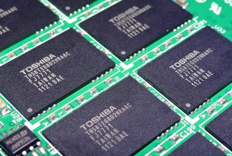
Both technologies increase storage density by storing multiple bits of data in each memory cell. However, they differ in how many bits each cell stores, how precisely the controller must distinguish between voltage states, and how the resulting design affects performance and endurance.
Neither TLC nor QLC is universally better. The right choice depends on the intended workload, capacity requirements, write activity, controller design and overall SSD architecture.
1. How TLC and QLC NAND Store Data
NAND flash stores information by representing data through different electrical states within memory cells. In multi-level cell designs, each cell can represent multiple bits by distinguishing between several threshold-voltage levels.
The number of bits stored in each cell determines how many distinct states must be represented.
| NAND Type | Bits per Cell | Possible Voltage States |
|---|---|---|
| SLC | 1 | 2 |
| MLC | 2 | 4 |
| TLC | 3 | 8 |
| QLC | 4 | 16 |
TLC stores three bits per cell, while QLC stores four. As a result, QLC can represent twice as many data combinations per cell as TLC.
This higher density allows manufacturers to store more data within a similar number of memory cells. It can help reduce the NAND cost per gigabyte, although the final SSD price also depends on manufacturing yields, controller and DRAM costs, firmware development, packaging, validation and market conditions.
The trade-off is that QLC must distinguish among more voltage states. As the number of states increases, the margins between adjacent states generally become narrower, making accurate programming and reading more demanding.
2. Storage Density and Cost per Gigabyte
Storage density is one of QLC’s primary advantages.
Because each QLC cell stores four bits instead of TLC’s three, a given number of cells can represent more user data. This makes QLC attractive for high-capacity storage products where cost per gigabyte is an important consideration.
For SSD manufacturers and system designers, QLC can help support higher-capacity drives without requiring a proportional increase in the number of memory cells.
However, cell-level density should not be confused with total SSD capacity. Actual usable capacity depends on the NAND die design, number of dies, over-provisioning, spare blocks, firmware configuration and formatting.
QLC’s density advantage also does not guarantee that every QLC SSD will be cheaper than every TLC SSD. Product pricing depends on the complete bill of materials, capacity, controller, cache configuration, performance targets and supply conditions.
TLC remains a strong option when a balance of capacity, write endurance and performance is required. QLC is especially attractive when higher capacity and cost efficiency are priorities.
3. Write Endurance and Data Retention
Write endurance refers to how much program/erase cycling NAND flash can withstand before wear begins to compromise its ability to store data reliably.
Each time a NAND block is erased and programmed again, its cells experience additional wear. Over time, this can increase error rates and require more intensive error correction.
TLC generally offers higher write endurance than comparable QLC NAND generations under similar operating conditions. QLC stores more bits per cell and must manage more closely spaced voltage states, which generally makes it more sensitive to cell wear and voltage variation.
Nevertheless, endurance is not determined by the NAND type alone. It also depends on:
- NAND generation and manufacturing process.
- Controller algorithms and error-correction capabilities.
- Write amplification and workload characteristics.
- Over-provisioning and available spare blocks.
- Operating temperature and usage conditions.
- Firmware behavior and wear-leveling efficiency.
Data retention is related to, but different from, write endurance. Retention describes how well programmed data remains readable over time, including when the drive is powered off. NAND wear, temperature and storage conditions can all affect retention.
For this reason, TLC and QLC products should be evaluated using their specified endurance ratings, retention requirements and intended workload rather than relying only on the cell classification.
4. Write Performance and Programming Complexity
TLC and QLC differ in how much information must be programmed and verified within each cell.
TLC must distinguish among eight voltage states, while QLC must distinguish among sixteen. Programming and reading these states accurately requires careful voltage control and sensing.
In general, QLC NAND has lower native write performance than comparable TLC NAND, particularly when writing directly to the flash cells. The exact difference depends on the NAND generation, operating mode, controller and drive configuration.
SSD controllers use multiple techniques to improve performance, including parallel access across NAND dies, command scheduling, buffering and caching. These techniques can make the real-world performance of two SSDs differ significantly even when they use the same NAND type.
Sequential read performance may also be competitive on well-designed QLC drives. Therefore, it would be inaccurate to assume that every QLC SSD is slow or that every TLC SSD is fast.
The key distinction is that QLC often requires more careful management to achieve high write performance, especially during sustained workloads.
5. SLC Caching and Sustained Write Speed
Many consumer SSDs use a portion of NAND flash in SLC mode to improve write performance. In this mode, each cell stores one bit rather than using its full TLC or QLC capacity.
Incoming data can first be written to this faster cache and then reorganized into the drive’s native storage format in the background.
This can substantially improve short-duration write performance. However, once the cache becomes full, the drive may need to write directly to native TLC or QLC cells while also managing data already stored in the cache.
As a result, sustained write speed can drop after the cache is exhausted.
QLC SSDs can be particularly sensitive to this behavior because their native programming performance and workload-dependent endurance characteristics may make long write operations more demanding. Yet the size of the performance drop varies considerably between products.
Important factors include:
- Cache size: Some drives use a fixed cache, while others allocate a variable amount based on available free space.
- Remaining capacity: A nearly full SSD may have less room for a dynamic cache.
- Background folding: Data written in SLC mode may need to be reorganized into the drive’s native NAND format.
- Controller and firmware: Scheduling and garbage-collection behavior affect how well the drive manages sustained activity.
- Workload: Short bursts of small files differ from large, continuous writes.
For this reason, peak benchmark results alone may not accurately represent performance during large file transfers, repeated content creation tasks or other write-intensive workloads.
6. TLC vs QLC: A Practical Comparison
| Characteristic | TLC NAND | QLC NAND |
|---|---|---|
| Bits per cell | 3 | 4 |
| Cell-level storage density | Lower than QLC | Higher than TLC |
| Cost efficiency at high capacities | Competitive | Potentially advantageous |
| Typical write endurance | Generally higher | Generally lower |
| Native write performance | Generally stronger | Often more limited |
| SLC cache importance | Significant | Often especially important |
| Read performance | Can be high | Can also be high |
| Typical design priority | Balanced performance and endurance | Capacity and cost efficiency |
These are general tendencies, not universal specifications. NAND generations and SSD implementations differ, so comparisons should ideally use products with similar capacity, interface, controller class and performance targets.
7. Choosing TLC or QLC for Different Workloads
The best NAND type depends on how the drive will be used.
Gaming and General PC Use
Both TLC and QLC SSDs can work well for operating systems, applications and games. Many of these workloads involve substantial reading, while the volume and pattern of writes vary by user.
For systems that regularly install large games, update software and transfer files, cache behavior and sustained write performance may matter more than the NAND label alone.
Large-Capacity Consumer Storage
QLC can be attractive for users who need substantial capacity for games, media libraries, archived projects and other data that is read frequently but written less intensively.
When choosing a QLC drive, buyers should still check endurance ratings, warranty terms, cache behavior and sustained write performance.
Content Creation and Frequent Large Writes
Workloads involving repeated large video exports, frequent file transfers, scratch-disk activity or other sustained writes can benefit from TLC’s generally stronger native write performance and endurance.
Actual requirements depend on daily write volume, project size and the drive’s workload rating. Some QLC drives may still be suitable for moderate content creation workloads, provided their specifications meet the usage requirements.
Enterprise and Write-Intensive Applications
For enterprise storage, databases, logging systems and other workloads with high write activity, endurance and predictable sustained performance are important selection criteria.
TLC is often a stronger starting point for these applications, but NAND type alone is insufficient. Workload-specific endurance ratings, power-loss protection, latency behavior, error recovery and system-level validation must also be considered.
QLC can serve appropriate read-intensive applications when its endurance and performance characteristics match the workload.
8. Why NAND Type Alone Does Not Determine SSD Quality
An SSD is a complete storage system, not simply a collection of NAND flash cells.
Two drives using TLC NAND can deliver very different results because of differences in their controllers, firmware, cache strategies, NAND configurations, thermal management and power behavior. The same principle applies to QLC products.
A meaningful comparison should therefore consider several dimensions together:
- NAND specifications: Cell type, generation, rated endurance and operating characteristics.
- Controller architecture: Parallelism, command scheduling, error correction and firmware support.
- Cache design: Cache size, allocation strategy and post-cache write performance.
- Thermal behavior: Whether sustained activity causes temperature-related performance reductions.
- Workload suitability: Expected write volume, access patterns and operating conditions.
- Product validation: Compatibility, sustained performance, error behavior and consistency under representative workloads.
For SSD designers and buyers, evaluating these factors provides a more reliable basis for selection than treating TLC or QLC as a standalone measure of quality.
Conclusion
TLC and QLC NAND flash represent different approaches to balancing storage density, endurance, performance and cost.
TLC stores three bits per cell and generally provides a stronger balance of write performance and endurance. QLC stores four bits per cell, increasing cell-level density and offering potential cost advantages for high-capacity storage.
Neither technology is universally superior. The right choice depends on the workload, capacity target, endurance requirements, sustained write behavior and the overall SSD design.
Understanding these trade-offs helps users select storage more effectively and helps product designers match NAND technology to the performance, reliability and cost requirements of each application.
The post TLC vs QLC NAND Flash: Density, Endurance and Performance appeared first on .
]]>The post Mixed RAM Configurations: Compatibility, Capacity and Performance Trade-Offs appeared first on .
]]>1. Introduction
Adding more RAM is a common way to increase a PC’s memory capacity, especially when existing memory is no longer sufficient for gaming, multitasking, content creation, or professional applications. However, upgrading memory is not always as simple as installing another module.
When users combine memory modules with different capacities, frequencies, timings, or specifications, the system must operate within the capabilities of the installed modules and the memory controller. In some cases, mixed configurations work without noticeable problems. In others, they may require lower operating speeds, additional compatibility checks, or manual configuration.
Mixing RAM does not automatically cause instability, nor does using modules from the same brand guarantee compatibility. The outcome depends on the complete memory configuration, including module characteristics, CPU memory-controller capabilities, motherboard design, BIOS support, and operating parameters.
Understanding these factors helps explain when mixing RAM is practical, what performance trade-offs may occur, and how to evaluate a memory upgrade more reliably.
2. What Does Mixing RAM Mean?
Mixed RAM configurations occur when a system uses memory modules that differ in one or more characteristics. These differences can include capacity, rated speed, timings, voltage requirements, memory rank, DRAM chip organization, or product series.
Common examples include:
- Combining an existing 8GB module with a new 16GB module.
- Installing a DDR4-3200 module alongside a DDR4-3600 module.
- Using modules with different CAS latency (CL) values.
- Combining memory modules from different manufacturers or product families.
- Adding a new module to an existing memory kit rather than replacing the original modules.
These configurations are not inherently incompatible. Many systems can operate with mixed modules, provided the modules are supported by the platform and can function together at a compatible set of operating parameters.
However, there is an important distinction between physical compatibility, successful startup, and long-term stability. A module may fit the motherboard and be detected correctly while the combined configuration still fails memory stress tests or cannot operate reliably at its intended performance settings.
3. Mixing RAM Capacities: 8GB, 16GB and 32GB Modules
Combining modules with different capacities can increase total system memory without requiring users to replace every existing module.
For example, installing an 8GB module alongside a 16GB module provides 24GB of nominal memory capacity, assuming the platform supports the configuration and both modules are recognized.
The effect on memory-channel operation depends on the platform’s memory architecture and how capacity is distributed across channels.
On many mainstream dual-channel systems, a configuration with unequal capacities can operate in a partially interleaved mode. If the system has 8GB on one channel and 16GB on the other, 8GB from each channel may form a 16GB interleaved region, while the remaining 8GB on the larger channel operates outside that symmetric region.
This behavior is commonly associated with Intel’s Flex Memory technology, although implementation details vary by platform.
The key point is that unequal capacity does not necessarily disable dual-channel operation entirely. Instead, some memory addresses may benefit from interleaving while others may operate with different channel-level characteristics.
Actual behavior depends on the CPU’s memory controller, motherboard layout, module placement, and platform-specific implementation. Users should consult the motherboard and processor documentation before assuming that a particular mixed-capacity arrangement will operate in a specific mode.
4. Mixing RAM Frequencies: Why the System May Run Slower
Memory modules often advertise different maximum data rates, such as DDR4-3200 and DDR4-3600. When these modules are installed together, the system must find an operating configuration that the modules and memory controller can support.
In many systems, mixed modules initially operate using compatible standard memory settings derived from their SPD information. The resulting data rate may be lower than the rated speed of the faster module.
For example, combining a DDR4-3200 module with a DDR4-3600 module does not mean the system will automatically run at 3600 MT/s. Depending on the platform, BIOS settings, and module capabilities, the system may operate both modules at 3200 MT/s or another mutually supported setting.
This is a common trade-off when mixing memory with different speed ratings: the faster module may not operate at its advertised maximum.
It is also important to distinguish a module’s rated profile from its guaranteed operating behavior on every system. XMP and EXPO profiles provide performance settings, but achieving those settings depends on CPU memory-controller capability, motherboard support, module configuration, and system stability.
A lower shared data rate is not necessarily a sign of defective RAM. It can simply be the result of the system choosing a more compatible operating configuration.
5. Mixing Memory Timings and Voltage Requirements
Memory timings describe delays associated with specific operations inside DRAM. Common examples include CAS latency (CL), tRCD, tRP, and tRAS.
When modules have different timing specifications, the system must use settings that are compatible with the installed configuration. Depending on the platform and configuration, this may involve selecting more relaxed timings or operating at a lower data rate.
For example, a module rated for DDR4-3200 CL16 and another rated for DDR4-3200 CL18 do not necessarily prevent the system from running at 3200 MT/s. The combined configuration may work with timings supported by both modules and the memory controller, but the exact result depends on their SPD information, voltage requirements, and BIOS implementation.
Voltage also matters. Modules that require different voltage settings for their advertised performance profiles may not operate reliably when the same settings are applied to both.
Users should avoid assuming that the fastest module’s timings and voltage can simply be applied to every installed module. A configuration that completes startup may still be unstable under sustained memory workloads.
For reliable operation, begin with standard supported settings, confirm stability, and only then consider enabling a performance profile or adjusting parameters.
6. Mixing RAM Brands and Product Series
Different RAM brands do not automatically mean incompatibility. Two modules from different manufacturers may use similar DRAM specifications and operate together successfully.
At the same time, using the same brand does not guarantee that two modules will behave identically.
Memory products within the same brand may use different DRAM ICs, PCB designs, module organizations, ranks, SPD configurations, or component revisions. Even products with similar labels may not have been validated as a single matched kit.
A memory kit is generally tested and sold as a set intended to operate together under specified conditions. Adding a separate module with similar specifications does not provide the same assurance as using a matched kit.
When evaluating mixed modules, it is more useful to compare their technical characteristics than to focus on the brand name alone.
Relevant factors include:
- DDR generation and supported platform.
- Capacity and module organization.
- Standard SPD settings.
- Rated data rate and timings.
- Voltage requirements.
- Rank configuration and DRAM organization.
- Motherboard and CPU compatibility.
The more closely the modules align in these characteristics, the easier it may be to find a shared operating configuration. However, matching specifications alone still cannot guarantee stability.
7. Single-Channel, Dual-Channel and Mixed-Capacity Operation
Memory-channel configuration affects the amount of data that can be transferred between the memory controller and DRAM in parallel.
A dual-channel configuration can provide more theoretical memory bandwidth than a comparable single-channel configuration when both channels are populated and operating appropriately. However, the performance benefit depends on the workload and platform.
When mixing capacities, the system may use an interleaved region across channels and a remaining region with a different channel-access pattern. This means that memory access behavior can vary depending on which addresses the application uses.
For example, a 16GB + 8GB configuration may provide more total capacity than a single 16GB module, and part of its memory space may operate in an interleaved configuration. The exact mapping and performance behavior depend on the platform.
This creates an important trade-off. Increasing total memory capacity can improve performance when the previous configuration was running out of RAM, even if the mixed configuration is not perfectly symmetric.
Conversely, a larger total capacity does not automatically mean higher memory bandwidth in every workload. Capacity, channel operation, data rate, timings, and application memory usage all influence the result.
8. Memory Rank and Module Organization
Memory rank is another factor that can differ between modules with similar capacity and speed ratings.
A rank is a group of DRAM devices accessed together as a unit by the memory controller. Depending on the platform, having multiple ranks may allow certain forms of rank interleaving, potentially improving memory-access efficiency.
However, rank count is not the same as memory-channel count, and more ranks do not guarantee better performance in every system.
Mixing single-rank and dual-rank modules may be supported, but the combined configuration can affect electrical loading on the memory controller. Higher loading may reduce the maximum stable data rate, particularly when multiple modules are installed per channel.
Module organization also matters. DRAM chip density, device width, and supported memory organization can influence whether a module is compatible with a particular CPU and motherboard.
For this reason, checking module specifications and platform documentation can be more informative than comparing only capacity and frequency.
9. Why Mixed RAM Can Cause Instability
A system may successfully detect all installed memory modules but still experience crashes, application errors, or intermittent startup failures.
Several factors can contribute to instability:
Different operating requirements: Modules may not share a stable combination of data rate, timings, and voltage at the selected settings.
Memory-controller limitations: The CPU’s integrated memory controller must support the combined module configuration. Four DIMMs or higher-capacity modules may place greater demands on the controller than a simpler configuration.
BIOS and training behavior: Firmware determines memory initialization and training behavior. Some combinations may require updated firmware or may train successfully only at lower settings.
Performance profiles: XMP or EXPO settings intended for a particular kit may not be suitable for a mixed configuration.
Module or slot problems: A defective module, poor contact, incompatible slot population, or motherboard issue can produce symptoms similar to mixed-memory instability.
When instability occurs, it is important to isolate the cause rather than assuming that all mixed configurations are unreliable.
10. How to Test a Mixed RAM Configuration
A structured testing process can help determine whether mixed memory operates reliably.
Step 1: Check platform support. Confirm the DDR generation, CPU memory-controller capabilities, motherboard specifications, and recommended DIMM slot population.
Step 2: Record module specifications. Compare capacity, standard SPD settings, rated data rate, timings, voltage, rank, and module organization where available.
Step 3: Install modules in the recommended slots. Follow the motherboard manual rather than assuming that any slot combination will provide the intended channel operation.
Step 4: Start with default memory settings. Disable XMP or EXPO temporarily and allow the system to initialize the memory using standard supported parameters.
Step 5: Confirm total capacity and operating settings. Check the capacity detected by the BIOS and operating system, along with the actual memory data rate.
Step 6: Run memory stability tests. Use a suitable memory-testing utility and test the system under realistic workloads. Successful startup alone is not enough to confirm stability.
Step 7: Adjust settings only if necessary. If the system is unstable, reduce the data rate or return to standard timings before attempting more aggressive settings.
Step 8: Re-test after every change. Test one adjustment at a time so that any improvement or failure can be attributed to a specific change.
This process helps distinguish configuration limitations from defective hardware and avoids unnecessary component replacement.
11. When Should You Mix RAM and When Should You Replace the Kit?
Mixing RAM can be a practical option when a system needs additional capacity and the existing modules remain suitable for the intended workload.
It may be reasonable when the user wants to add memory economically, does not require maximum overclocking performance, and can verify that the resulting configuration is stable.
Replacing the existing kit with a matched set may be preferable when:
- The system requires predictable operation for professional or business-critical workloads.
- The existing modules differ substantially in their specifications.
- The user wants to achieve a particular high-speed XMP or EXPO profile.
- The platform is sensitive to DIMM count or memory loading.
- Troubleshooting time and reliability matter more than the cost of reusing existing modules.
A matched kit reduces some configuration uncertainty because its modules are intended to work together. However, even matched kits must operate within the supported capabilities of the CPU and motherboard.
The best choice depends on the balance between total capacity, performance requirements, budget, and stability expectations.
Conclusion
Mixed RAM configurations can provide a practical way to expand system memory, but the result depends on more than whether the modules fit the motherboard.
Different capacities may lead to partially interleaved memory regions, different speed ratings may result in a lower shared data rate, and differences in timings, voltage, rank, or module organization can affect compatibility and stability.
The most important distinction is between a configuration that boots and one that operates reliably under sustained workloads.
By checking platform support, comparing module specifications, starting with standard settings, and testing stability systematically, users can make more informed decisions about memory upgrades.
For systems that require predictable performance, a compatible matched kit remains a straightforward choice. For systems where cost-effective capacity expansion is the priority, mixing RAM can also work well when the complete configuration is properly supported and validated.
The post Mixed RAM Configurations: Compatibility, Capacity and Performance Trade-Offs appeared first on .
]]>The post External SSD Performance: USB Interfaces, Protocols and Real-World Speeds appeared first on .
]]>1. Introduction
External SSDs offer a convenient way to expand storage, transfer large files, back up important data, and move data between computers. Compared with traditional external hard drives, they can provide much higher transfer speeds, smaller form factors, and better resistance to everyday movement.
However, not all external SSDs deliver the same performance. Two drives with similar advertised specifications may produce noticeably different results in real-world use, even when they have the same storage capacity.
The reason is that external SSD performance depends on more than the internal drive itself. The USB interface, host port, connection cable, enclosure controller, communication protocol, and NAND flash configuration all contribute to the final transfer rate.
Understanding how these components work together helps explain why an external SSD advertised at 10 Gbps may not deliver 1,000 MB/s in every situation, and why selecting a faster internal SSD does not automatically guarantee faster external storage.
2. USB Connector Types and Transfer Speeds Are Different
One of the most common sources of confusion is the difference between a USB connector and the transfer rate supported by the connection.
USB Type-A and USB Type-C describe connector designs. They do not, by themselves, determine how fast data can move between a computer and an external SSD.
USB Type-C is widely used for modern external storage because it supports a compact, reversible connection and can carry data through different USB implementations. However, two Type-C ports may support different maximum data rates.
For example, a computer’s USB-C port might support 5 Gbps, 10 Gbps, 20 Gbps, or a higher rate under a supported USB4 or Thunderbolt configuration. Another Type-C port on the same computer might offer different capabilities.
The same principle applies to USB Type-A. Its physical shape does not guarantee a specific transfer speed either.
When evaluating an external SSD, it is important to check the supported USB standard and maximum data rate of both the host port and the storage device, rather than relying on the connector shape alone.
3. Understanding USB Data Rates and Theoretical Throughput
USB interface specifications are commonly expressed in gigabits per second (Gbps), while SSD transfer speeds are usually reported in megabytes per second (MB/s).
Because one byte contains eight bits, converting the advertised data rate into a theoretical byte rate requires dividing by eight.
| USB data rate | Theoretical maximum before protocol overhead |
|---|---|
| 5 Gbps | 625 MB/s |
| 10 Gbps | 1,250 MB/s |
| 20 Gbps | 2,500 MB/s |
| 40 Gbps | 5,000 MB/s |
These figures represent theoretical limits based on the stated signaling rate. They are not guaranteed file-transfer speeds.
USB protocols introduce encoding and communication overhead, while storage operations also require command processing and data management. Consequently, usable throughput is lower than the theoretical maximum.
For a USB 3.2 Gen 2 connection rated at 10 Gbps, an external SSD may achieve sequential transfer speeds around or above 1,000 MB/s under suitable conditions, depending on the enclosure, internal SSD, host controller, workload, and benchmark method. Actual results vary by product and system.
A 10 Gbps interface therefore provides a useful performance reference, but it does not guarantee that every external SSD will reach the same speed.
4. USB Protocols and SSD Communication
The communication protocol determines how the host system sends commands to the storage device and how the device responds.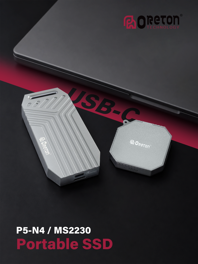
External SSDs commonly use one of two storage protocols: USB Mass Storage Bulk-Only Transport (BOT) or USB Attached SCSI Protocol (UASP).
BOT is an older transport method that handles storage commands through a more serialized process. UASP supports more efficient command handling, including command queuing, which can improve performance in suitable workloads.
UASP can be particularly helpful when the system performs multiple storage operations or accesses many small files. However, the benefit depends on support from the host operating system, USB controller, enclosure bridge, and storage device.
A USB connection running at 10 Gbps does not automatically mean that UASP is active or that the complete storage path is optimized. Compatibility across the host, enclosure, and operating system still matters.
For external NVMe SSDs, the enclosure controller commonly bridges the NVMe interface to USB. The bridge must support the relevant protocols and provide enough processing capability to handle the intended data rate.
5. The Role of the External SSD Enclosure and Bridge Controller
An external SSD enclosure is more than a protective shell. Its bridge controller manages communication between the internal SSD and the computer’s USB interface.
The controller translates commands between the host-facing USB connection and the internal storage interface, such as SATA or PCIe/NVMe. Its capabilities can affect maximum throughput, command handling, compatibility, power management, and thermal behavior.
Different enclosure designs may support different storage interfaces and USB speeds. For example, an enclosure built for a SATA SSD cannot deliver the same performance as a high-speed NVMe enclosure simply by using a faster USB cable.
The bridge controller can also become a bottleneck. If the internal SSD supports much higher speeds than the enclosure’s USB interface, the external drive will be limited by the enclosure and host connection.
Compatibility is another consideration. An enclosure must support the internal drive’s physical form factor and interface. M.2 is a form factor, not a guarantee of SATA or NVMe compatibility, so the enclosure’s supported protocol must be verified before installation.
6. How the Internal SSD Affects External Performance
Even with a fast USB interface and a capable enclosure, the internal SSD remains an important part of the performance equation.
External storage can use SATA SSDs or NVMe SSDs. SATA SSDs are limited by the SATA interface, while NVMe SSDs can support much higher internal transfer rates through PCIe.
Consider a 10 Gbps USB enclosure. If the internal drive is a SATA SSD, the SATA interface will generally limit sequential throughput before the USB connection reaches its full usable capacity. A suitable NVMe SSD may better utilize the available USB bandwidth.
However, a faster NVMe drive does not always produce a proportionally faster external SSD. Once the USB connection or bridge controller becomes the bottleneck, additional internal SSD bandwidth cannot translate into higher host transfer speeds.
Internal SSD behavior also matters during long write operations. Some SSDs use a fast pseudo-SLC cache to accelerate writes. After that cache fills, write speed may decline depending on NAND type, remaining free space, controller behavior, and background data management.
As a result, a short benchmark may show a high peak speed while a longer file transfer produces a lower average rate.
7. Cable Quality and Host Port Limitations
The cable is another part of the data path that can affect external SSD performance.
A USB-C connector does not guarantee that the cable supports the same data rate as the SSD enclosure. Some cables are designed primarily for charging or lower-speed data transfer, while others support higher-speed USB connections.
Using a cable with insufficient data-rate support can prevent an external SSD from reaching its intended performance. Cable length, implementation quality, and signal integrity can also affect the reliability of high-speed connections.
The host port matters just as much. An external SSD rated for 10 Gbps will not achieve its intended interface speed when connected through a port limited to 5 Gbps.
Additional adapters, hubs, or docking stations may introduce further limitations. Their supported data rates, internal controllers, and shared bandwidth should be considered when troubleshooting unexpectedly low speeds.
For the most reliable performance, connect the external SSD directly to a compatible host port using a cable rated for the enclosure’s supported data rate.
8. Why Real-World Transfer Speeds Differ from Benchmarks
Benchmark results are useful for comparing storage devices, but they do not always reflect the speed users experience when transferring everyday files.
Sequential benchmarks typically measure the transfer of large, continuous blocks of data. These workloads are useful for estimating performance during large file copies, video transfers, and similar operations.
Small-file workloads behave differently. They involve more individual storage operations, metadata handling, and command processing. In these scenarios, latency, queue depth, file-system behavior, and protocol efficiency can matter more than the maximum sequential transfer rate.
Other factors can also influence results:
- Write cache behavior: Short tests may finish before an SSD’s write cache becomes saturated.
- Drive temperature: Sustained workloads may trigger thermal throttling in the SSD or enclosure.
- Available storage space: SSD performance can vary with capacity utilization and internal data-management activity.
- Host system workload: CPU activity, background processes, and other storage operations may affect measured throughput.
- File size and file count: Copying one large file can produce different results from copying thousands of small files.
- Power management: USB power-saving behavior and device power requirements may affect operation in certain systems.
A meaningful performance evaluation should therefore include both sequential and relevant real-world workloads, rather than relying on one peak-speed figure.
9. Choosing the Right USB Interface for Different Workloads
The most suitable USB interface depends on the required transfer speed, the type of work being performed, and the equipment already available.
| USB interface rate | General positioning | Typical considerations |
|---|---|---|
| 5 Gbps | Everyday external storage | Backups, documents, photos, and general file transfers |
| 10 Gbps | Higher-speed portable storage | Large file transfers, media libraries, and regular data movement |
| 20 Gbps | Higher-bandwidth external storage | Workloads that benefit from additional USB bandwidth and compatible host support |
| 40 Gbps | Very high-bandwidth external storage | Specialized workflows requiring a compatible USB4 or Thunderbolt implementation |
These categories are general guidelines, not strict workload requirements. Even a 5 Gbps drive can be suitable for many users, while a 40 Gbps enclosure may offer little practical benefit if the internal SSD, host port, or workload cannot take advantage of the additional bandwidth.
For users who regularly transfer large video files or work with extensive media libraries, a 10 Gbps or faster connection may reduce transfer times. For everyday backups and document storage, cost, capacity, portability, and compatibility may be more important than maximizing interface speed.
10. A Practical Checklist for Evaluating External SSD Performance
When comparing external SSDs or troubleshooting unexpectedly low transfer rates, evaluate the entire connection rather than looking at a single specification.
- Check the host port. Confirm the USB standard and supported data rate.
- Verify the cable. Ensure it supports the intended data rate, not just the correct connector.
- Confirm enclosure compatibility. Check whether the enclosure supports SATA or NVMe and the relevant drive form factor.
- Review the bridge controller. Confirm the supported interface speed and protocol features.
- Identify the internal SSD. Consider its interface, sequential performance, cache behavior, and sustained-write characteristics.
- Test realistic workloads. Compare large-file transfers with smaller-file operations and longer write sessions.
- Monitor temperature and system behavior. Check for thermal throttling, background activity, or power-related limitations.
This approach makes it easier to identify the component limiting performance and helps prevent unnecessary upgrades to parts that are not responsible for the bottleneck.
Conclusion

External SSD performance is determined by the complete data path, from the computer’s USB port to the enclosure controller and the internal storage device.
Connector type, USB data rate, communication protocol, cable capability, bridge-controller design, and SSD architecture all influence the final result. A high advertised interface speed provides useful information, but it does not guarantee equivalent real-world transfer performance.
For reliable comparisons, evaluate the supported USB standard alongside the enclosure and internal SSD specifications, then verify performance under workloads that reflect actual usage.
Understanding these factors helps users select external storage solutions that balance speed, compatibility, and cost without paying for bandwidth their system cannot use.
The post External SSD Performance: USB Interfaces, Protocols and Real-World Speeds appeared first on .
]]>The post BIOS and Firmware: Their Impact on PC Hardware Compatibility appeared first on .
]]> Modern PCs rely on more than physical hardware to operate correctly. A CPU, motherboard, memory module, SSD, and graphics card must work together through a combination of hardware interfaces, configuration data, firmware, and operating system software.
BIOS and other firmware components play a critical role in this process. They initialize hardware, configure system resources, identify installed devices, and prepare the platform to load an operating system. Their implementation can influence whether a component is recognized, whether a system starts successfully, and whether supported hardware configurations operate reliably.
Two PCs with similar hardware may behave differently if they use different firmware versions or configuration settings. A memory module may require updated platform support, an SSD may depend on the system’s storage configuration, and a CPU may need a compatible motherboard firmware version before it can initialize correctly.
Understanding how BIOS and firmware work helps explain why hardware compatibility depends on both physical specifications and the software embedded within the platform.
2. BIOS and Firmware: Understanding the Difference
Firmware is software stored in non-volatile memory that controls or initializes hardware. Unlike ordinary applications, firmware operates close to the hardware and provides functions that allow devices or systems to start and operate.
BIOS stands for Basic Input/Output System. On modern PCs, the term is often used informally to refer to the motherboard’s firmware setup environment.
Historically, traditional BIOS firmware was responsible for initializing hardware and starting the operating system. Most modern PCs use UEFI (Unified Extensible Firmware Interface), which provides a more flexible firmware environment and supports modern boot mechanisms, including GPT-based boot configurations and Secure Boot.
The terms BIOS and UEFI are frequently used interchangeably in everyday PC discussions, although they refer to different firmware approaches.
Firmware also exists outside the motherboard. Examples include firmware inside SSD controllers, graphics cards, network adapters, and other peripherals. Each implementation controls functions specific to its device.
The distinction matters because compatibility issues can originate from different layers. A motherboard firmware update may improve platform-level hardware support, while an SSD firmware update may address device-specific behavior.
3. The Role of Firmware During System Startup
When a PC is powered on, the processor begins executing instructions from a predefined reset location associated with the platform’s firmware environment.
The motherboard firmware then performs a series of initialization tasks before transferring control to the operating system’s boot process.
Although the exact sequence varies by platform, startup generally involves several stages:
- Platform initialization: The firmware configures essential processor, chipset, and motherboard functions.
- Memory initialization: The system detects installed memory and establishes working memory parameters.
- Device discovery: The firmware identifies and configures supported hardware, including storage devices and expansion components.
- Hardware checks: The platform performs initialization checks and reports certain errors when hardware cannot be configured successfully.
- Boot device selection: The firmware identifies an available boot target according to the configured boot order and boot options.
- Operating system loading: The firmware transfers control to the selected bootloader, which begins loading the operating system.
A problem at any of these stages can prevent the PC from starting normally.
For example, an incompatible CPU may fail to initialize, unstable memory settings may prevent successful POST, or an incorrect boot configuration may cause the system to report that no bootable device is available.
These symptoms can appear similar to hardware failure, even when the underlying cause is a firmware or configuration issue.
4. Hardware Recognition and Initialization
A PC contains many components that must be identified and configured before they can be used.
Motherboard firmware initializes the platform and discovers devices through supported interfaces. It may configure PCIe resources, establish storage access paths, and provide information that later software uses to identify hardware.
However, hardware recognition does not guarantee that every function will operate correctly.
For example, a system may detect an NVMe SSD but still fail to boot from it because the boot configuration is incorrect, the required bootloader is missing, or the operating system does not have the necessary support.
Similarly, a graphics card may be electrically compatible with a PCIe slot but still encounter problems related to firmware support, platform configuration, or device-specific software.
Compatibility should therefore be considered at multiple levels:
- Physical compatibility: The component fits and can be connected correctly.
- Electrical and interface compatibility: The component uses an interface supported by the platform.
- Firmware compatibility: The platform can initialize and configure the component.
- Operating system compatibility: The required drivers and software support are available.
- Functional compatibility: The component performs its intended tasks correctly under real workloads.
A successful hardware detection step is only one part of the overall compatibility process.
5. Memory Training and BIOS Configuration
Memory initialization is one of the most important firmware tasks in a modern PC.
Before the operating system can use system memory, the platform must configure the memory controller and establish suitable operating parameters for the installed DIMMs.
Depending on the platform, memory initialization and training can involve determining appropriate signal timing, calibration values, and other electrical parameters needed for reliable communication between the memory controller and DRAM.
The process depends on several factors, including:
- CPU memory controller capabilities
- DDR generation and supported data rates
- Memory module organization and Rank configuration
- Number of installed DIMMs
- Motherboard signal routing and electrical characteristics
- Firmware implementation and configuration settings
This explains why a memory kit that works with one CPU and motherboard combination may not behave identically on another platform.
Higher memory data rates and more demanding DIMM configurations can increase the difficulty of establishing stable operation. A system may require additional training time, use different trained parameters, or fall back to a lower operating speed when the selected configuration cannot initialize successfully.
Memory training is not simply a one-time performance optimization. It is part of the process that allows the platform to establish reliable communication with installed memory.
6. XMP, EXPO, and Memory Profiles
Many DDR4 and DDR5 memory modules support performance profiles such as Intel XMP or AMD EXPO, depending on the product and platform.
These profiles provide predefined memory settings, which may include data rate, timings, and voltage parameters. Compatible firmware can read the available profile information and apply the selected configuration.
However, a profile is not an unconditional guarantee that every system will operate at the advertised settings.
Actual support depends on the CPU memory controller, motherboard design, firmware version, DIMM population, and the particular memory kit.
A system may boot successfully using standard memory settings but fail to initialize after a high-performance profile is enabled. This can occur when the selected configuration exceeds the stable operating capability of the combined platform.
When troubleshooting, returning to default or standard memory settings can help determine whether the issue is associated with the performance profile rather than the physical memory module itself.
It is also important to distinguish between a module’s advertised profile and the memory controller’s official supported specifications. A profile may represent an overclocked memory configuration rather than a guaranteed operating point for every CPU and motherboard combination.
7. CPU and Motherboard Firmware Compatibility
CPU compatibility depends on more than the socket.
A motherboard must have the appropriate electrical design, chipset support, power delivery, and firmware implementation to initialize a particular processor.
Some motherboard models require a minimum BIOS or UEFI version to support newer CPU models, even when those processors use the same physical socket.
If the installed firmware does not recognize or properly initialize the processor, the system may fail to complete POST. Depending on the motherboard, diagnostic LEDs, beep codes, or display messages may help identify the problem.
Firmware updates can add processor support, correct initialization issues, or improve compatibility with certain configurations. However, support depends on the exact motherboard model and the firmware release.
Before installing a CPU, it is therefore important to check the motherboard manufacturer’s CPU support list and the minimum required firmware version.
8. Storage Compatibility and Boot Configuration
Firmware also influences how a PC detects storage devices and starts an operating system from them.
Modern systems commonly use NVMe SSDs connected through PCIe, as well as SATA storage devices. These interfaces follow different communication mechanisms, and their configuration depends on the motherboard and platform.
An NVMe SSD may be physically installed in an M.2 slot but remain unavailable for booting if the slot does not support the expected interface, the device is not initialized correctly, or the boot environment is configured improperly.
Boot configuration is another important factor. UEFI systems typically use boot entries that point to an operating system bootloader, often stored on an EFI System Partition. Changing boot mode, boot order, or related settings can prevent an otherwise functional installation from starting.
Secure Boot and storage configuration can also affect the startup process, depending on the operating system and installed software.
When a PC cannot boot from an SSD, troubleshooting should distinguish between device detection, bootloader availability, firmware configuration, and operating system problems rather than assuming that the SSD itself has failed.
9. Firmware Updates and Hardware Support
Firmware updates can improve compatibility, address bugs, refine hardware initialization, and add support for new components.
For motherboards, updates may include CPU microcode changes, memory compatibility improvements, updated initialization routines, security fixes, and adjustments to power or device behavior.
SSD and graphics card firmware updates address different layers of device operation and may fix controller-specific or device-specific issues.
However, newer firmware does not automatically improve every system. A release may target a particular processor generation, memory configuration, security issue, or hardware problem.
Before updating firmware, users should review the release notes and confirm that the update applies to their exact hardware model.
Important precautions include:
- Verify the exact motherboard or device model and hardware revision.
- Download firmware from the appropriate manufacturer’s support page.
- Read update instructions and relevant release notes.
- Avoid interrupting power during the update process.
- Record important firmware settings before updating.
- Confirm whether the update changes memory, storage, security, or boot defaults.
Some firmware updates reset configuration settings, change memory training behavior, or require a subsequent initialization cycle. These effects should be considered when evaluating a system after an update.
10. Firmware Settings and System Stability
Firmware settings determine how a platform configures many of its hardware functions.
Memory frequency and timings, CPU power behavior, boot mode, Secure Boot, virtualization support, and certain PCIe settings may all be controlled or exposed through the firmware setup interface.
An incorrect setting can create instability even when all installed components are individually compatible.
For example, an aggressive memory profile may cause repeated boot failures, while a changed boot mode may prevent an existing operating system installation from starting.
Changes to CPU power limits or voltage-related parameters can also affect temperatures, power consumption, and stability.
When a system becomes unstable after a configuration change, restoring default settings can help isolate the cause. However, resetting firmware settings may also change storage or security configurations, so the original setup should be recorded when necessary.
Stable operation depends on selecting settings that are supported by the complete platform, not simply enabling the most aggressive available options.
11. Common Firmware-Related Compatibility Problems
Several common PC problems can originate from firmware, configuration, or initialization issues.
System fails to POST after a memory upgrade
Possible causes include incomplete memory training, unsupported settings, improper DIMM installation, or a configuration that exceeds the platform’s stable operating capability.
PC does not recognize a newly installed CPU
The motherboard may require a newer firmware version, or the processor may not be supported by the specific board model.
SSD is detected but the operating system will not boot
The issue may involve boot order, UEFI configuration, a missing bootloader, or operating system startup files rather than the SSD’s physical condition.
System becomes unstable after enabling XMP or EXPO
The selected memory profile may not be stable on the current CPU, motherboard, and DIMM configuration.
A hardware device behaves differently after a firmware update
The update may have changed defaults, initialization behavior, compatibility rules, or device-specific operation. Reviewing the release notes and comparing settings can help identify the difference.
In all these cases, the most effective troubleshooting approach is to isolate one variable at a time and verify the relevant hardware and firmware support information.
12. A Structured Approach to Firmware Troubleshooting
Firmware-related problems are easier to diagnose when the troubleshooting process follows a consistent order.
First, verify the physical installation. Check that the CPU, DIMMs, SSD, graphics card, and power connectors are installed correctly.
Second, confirm the exact hardware models and supported configurations. Check CPU support lists, memory specifications, motherboard documentation, and interface requirements.
Third, restore a known-good configuration when safe to do so. Standard memory settings and default firmware values can help determine whether a problem results from custom settings.
Fourth, identify the stage at which the failure occurs. A system that cannot complete POST requires a different diagnostic approach from one that starts normally but cannot load its operating system.
Finally, consider a firmware update only when there is a relevant compatibility reason, documented fix, or specific requirement. Follow the manufacturer’s instructions and avoid unnecessary firmware changes during troubleshooting.
This approach reduces the risk of introducing additional problems while helping distinguish hardware faults from configuration issues.
Conclusion
BIOS and firmware are essential parts of modern PC hardware compatibility. They initialize components, configure system resources, manage memory training, identify devices, and prepare the system to load an operating system.
A component’s physical interface and advertised specifications do not tell the whole story. Reliable operation also depends on processor support, motherboard implementation, firmware version, configuration settings, and operating system support.
Understanding these relationships makes it easier to select compatible hardware, diagnose startup problems, configure memory correctly, and evaluate firmware updates.
PC compatibility is not determined by hardware specifications alone. It depends on how hardware, firmware, configuration, and software work together as a complete system.
The post BIOS and Firmware: Their Impact on PC Hardware Compatibility appeared first on .
]]>The post SSD Capacity Planning for Modern PC Systems appeared first on .
]]>SSD capacity is an important factor in modern PC configuration. While SSD performance is often measured by sequential read and write speeds, capacity determines how much data a system can store locally and how much flexibility users have as their applications, games, and files grow over time.
A 512GB SSD may be sufficient for an office computer with lightweight applications, while a gaming PC or content creation workstation may benefit from 1TB, 2TB, or more. Systems used for local AI workloads can also require additional storage for models, datasets, and generated files.
Choosing an appropriate SSD capacity requires more than estimating the size of the operating system. It involves considering application requirements, workload characteristics, available free space, future expansion, and the role of other storage devices.
2. Understanding SSD Capacity and Usable Space
SSD capacity is typically advertised in decimal units, where 1GB equals 1 billion bytes and 1TB equals 1 trillion bytes. Operating systems commonly display storage capacity using binary-based calculations, although the displayed unit labels may vary.
As a result, a drive marketed as 1TB may appear as approximately 931GiB when measured using binary units. This difference is caused by the calculation method rather than missing storage capacity.
The capacity available for personal files will also be lower than the total reported drive capacity after accounting for the operating system, installed applications, recovery partitions, and other system data.
For example, a PC with a 1TB SSD may initially have enough space for the operating system, common applications, and a moderate file library. However, the remaining capacity can decrease significantly as large games, project files, caches, and media libraries accumulate.
For accurate planning, it is useful to distinguish between three values:
- Advertised capacity: The nominal capacity specified by the drive manufacturer.
- Usable capacity: The space recognized by the operating system and available after formatting and partitioning.
- Free capacity: The space remaining after system files, applications, and user data occupy storage.
Free capacity is the most relevant figure for everyday storage planning.
3. Operating System and Application Requirements
The operating system is only one part of a PC’s total storage demand. Windows installation files, updates, temporary files, recovery data, and system components all contribute to storage usage over time.
Applications add another layer of demand. Office software and lightweight utilities generally require relatively little space compared with professional creative applications, development environments, and large software suites.
Application storage requirements also extend beyond the installation directory. Updates, downloaded components, temporary files, browser caches, and application-generated data can gradually consume additional space.
A 512GB SSD can support a basic system with a moderate application library, but it offers less flexibility when the number and size of installed applications increase. A 1TB SSD provides more room for software, personal files, and future updates without requiring frequent storage management.
The appropriate capacity therefore depends on the complete software environment rather than the operating system alone.
4. SSD Capacity Planning for Gaming PCs
Modern PC games can require substantial storage space. High-resolution textures, detailed environments, downloadable content, frequent updates, and additional language packs can all increase installation size.
A gaming PC’s storage demand also depends on how many games are installed simultaneously. A user who regularly plays two or three titles may have very different requirements from someone who maintains a large game library across several launchers.
512GB SSD: Suitable for a compact gaming setup with a limited number of installed games. Space can become restrictive when several large titles and other applications share the same drive.
1TB SSD: A practical starting point for many mainstream gaming systems. It provides more flexibility for multiple games, updates, and everyday applications.
2TB SSD: Better suited to users who maintain a larger game library, install multiple demanding titles, or prefer to keep more games available without repeatedly uninstalling them.
4TB and above: Useful for extensive game libraries, large local media collections, and systems where storage expansion is inconvenient.
These capacities are general planning guidelines rather than fixed requirements. Actual demand varies according to the games installed, update behavior, and whether other drives are available.
5. SSD Capacity for Content Creation
Content creation workloads can generate much larger files than typical office applications. Video footage, high-resolution photographs, audio recordings, 3D assets, and project caches may occupy significant storage space.
Video editing is particularly storage-intensive because projects can include original footage, proxy files, previews, rendered output, and multiple project versions. Higher resolutions, higher bitrates, and longer recording sessions increase storage requirements.
Photography workflows also accumulate data through RAW files, edited versions, previews, catalogs, and backups. Similarly, 3D design and animation can involve large textures, source assets, simulations, and rendered sequences.
For these workloads, SSD capacity should be planned around both the active project and the surrounding workflow.
A 1TB SSD may be sufficient for light creative work or smaller projects. A 2TB drive offers more room for active video projects, photography libraries, and larger asset collections. More demanding professional workflows may require 4TB or greater capacity, particularly when substantial source files need to remain locally accessible.
It is also important to distinguish active working storage from long-term archival storage. Not every completed project needs to remain on the primary SSD indefinitely.
6. SSD Capacity for Local AI Workloads
Local AI applications introduce another source of storage demand. Depending on the software and task, a system may need to store model files, datasets, vector databases, application dependencies, cached data, and generated outputs.
Individual model files can range from relatively small downloads to many gigabytes or more. Multiple model versions, quantization variants, and specialized models can quickly increase total storage usage.
Dataset requirements vary even more widely. Small experimental datasets may occupy limited space, while image collections, audio corpora, and large language or multimodal datasets can require substantial local storage.
For a PC used primarily for everyday applications with occasional local AI experiments, 1TB may provide a reasonable starting point. A system intended to maintain multiple models and datasets may benefit from 2TB or more.
The key consideration is that AI storage demand depends on the number and size of locally retained models and datasets, not simply on whether the PC is described as an AI PC.
Storage capacity should also be considered separately from system memory and GPU memory. A larger SSD allows more files and models to be stored locally, but it does not directly increase the amount of RAM or VRAM available during model execution.
7. Capacity Requirements for Office and General-Purpose PCs
Office systems typically have more predictable storage requirements than gaming or creative workstations.
Documents, spreadsheets, presentations, browser data, email archives, and standard business applications generally require less space than large games or media projects. However, local databases, virtual machines, large offline files, and extensive email archives can change the overall requirement.
A 512GB SSD can be sufficient for many office PCs, especially when most documents are stored in managed cloud services or on network storage.
A 1TB SSD provides additional flexibility for users who retain more data locally, install specialized applications, or need room for future software and file growth.
For general-purpose systems, the decision should reflect the actual local storage workload rather than assuming that every PC requires the same capacity.
8. Maintaining Free Space on an SSD
SSD capacity planning should include a reasonable allowance for future data growth and routine system operations.
When a drive approaches full capacity, users may have less room for application updates, temporary files, downloads, and new projects. Some workloads may also experience reduced performance when free space is very limited, depending on the SSD design, controller behavior, workload, and cache management.
There is no single free-space percentage that guarantees optimal performance for every SSD. The appropriate reserve depends on the drive and how it is used.
For general-purpose planning, keeping approximately 10–20% of the drive free can be a useful starting guideline, especially for systems with frequent updates or write-intensive workloads. It is not a universal technical requirement, and some workloads may need a larger reserve.
The purpose of this reserve is to preserve flexibility for new data and system operations, rather than treating all advertised capacity as space that should be permanently occupied.
9. SSD Capacity and Storage Expansion
The number of storage devices supported by a PC depends on its motherboard, available M.2 slots, SATA connectors, PCIe lane allocation, physical space, and platform limitations.
Some systems allow users to add another M.2 NVMe SSD, while others provide additional SATA connectivity or limited expansion options. Certain M.2 slots may also share resources with other interfaces, so motherboard documentation should be checked before planning an upgrade.
When a system supports multiple drives, storage can be divided by purpose. For example, one SSD can hold the operating system and applications, while another stores games, active projects, or large datasets.
This arrangement can improve organizational flexibility and simplify storage upgrades. However, using multiple drives does not automatically improve application performance; the benefit depends on workload placement, interface capabilities, and how the drives are used.
When expansion is limited or inconvenient, selecting a larger primary SSD at the beginning can reduce the need for future migration.
10. SSD Capacity and Long-Term Usage
Storage demand rarely remains constant throughout a PC’s service life.
Operating systems receive updates, applications introduce new features, games expand through downloadable content, and personal file libraries continue to grow. Creative projects may also need to be retained for revisions, while local AI workflows can accumulate model versions and datasets.
Capacity planning should therefore account for expected growth rather than only current usage.
A useful approach is to estimate the initial storage requirement, add the expected size of applications and data that will be retained locally, and then reserve additional space for future growth.
For systems with predictable workloads, this estimate can be relatively straightforward. For gaming, creative work, and AI experimentation, a larger margin may be appropriate because file sizes and usage patterns can change considerably.
11. Comparing 512GB, 1TB, 2TB, and 4TB SSDs
The following table summarizes common capacity choices by their typical use cases.
| SSD capacity | Typical use cases | Main consideration |
|---|---|---|
| 512GB | Office PCs, general-purpose systems, compact application libraries | Lower initial storage cost, but less room for large games and projects |
| 1TB | Mainstream PCs, moderate gaming, everyday creative work | A flexible balance for many common workloads |
| 2TB | Gaming libraries, larger creative projects, local AI models | More room for data growth and locally retained files |
| 4TB or more | Large media libraries, demanding creative workflows, extensive local datasets | Higher capacity for workloads with substantial ongoing storage demand |
These categories are not strict boundaries. A 512GB SSD can support a gaming PC with a limited library, while an office workstation may need 2TB or more if it stores large databases or media archives.
Capacity should always be selected according to the actual workload, retention requirements, and available expansion options.
12. Capacity Is Only One Part of SSD Selection
A larger SSD provides more storage space, but capacity alone does not determine overall performance.
SSDs with the same nominal capacity can differ in NAND type, controller architecture, cache behavior, interface, endurance, and sustained write performance.
Workload also matters. A system used primarily for document access may have very different performance requirements from one that frequently writes large video files or manages extensive datasets.
Interface compatibility must also be considered. An M.2 form factor does not automatically mean that a drive supports NVMe, and an NVMe SSD’s PCIe generation must be compatible with the host platform. Supported drive sizes, keying, and motherboard limitations should be checked as well.
For this reason, capacity planning should be performed alongside performance and compatibility evaluation, not as an isolated decision.
Conclusion
SSD capacity planning begins with understanding how a PC will be used and how much data needs to remain locally accessible.
A 512GB SSD can suit many office and general-purpose systems. A 1TB drive provides greater flexibility for mainstream PC use and moderate gaming. A 2TB or larger SSD is more appropriate for extensive game libraries, content creation, local AI models, and other storage-intensive workloads.
The most suitable capacity is not necessarily the largest available option. It is the capacity that meets current requirements, allows reasonable room for growth, maintains sufficient free space, and fits the system’s storage expansion capabilities.
By considering operating system requirements, applications, games, creative files, AI workloads, and long-term data growth together, users can make more informed SSD capacity decisions for modern PC systems.
The post SSD Capacity Planning for Modern PC Systems appeared first on .
]]>The post Gaming PC Memory Architecture: Capacity, Frequency and Timings appeared first on .
]]>Two memory kits can have the same capacity and frequency while delivering different levels of performance because memory timings, channel configuration, rank organization, the CPU memory controller, motherboard design, BIOS settings, and game workloads can all influence the final result.
For gaming PC manufacturers, OEMs, system integrators, and hardware distributors, understanding these factors helps create memory configurations that balance performance, compatibility, stability, and cost.
1. The Role of Memory in a Gaming PC
During gaming, system memory temporarily stores game data, application data, operating system resources, and other information required by the CPU.
The CPU continuously accesses memory while processing game logic, physics, AI, background tasks, and other workloads.
A gaming PC therefore needs enough memory capacity to keep the required data available while providing sufficient bandwidth and low enough latency for the platform.
However, memory is only one part of the complete gaming system.
CPU performance, GPU performance, storage, motherboard design, and software optimization can all have a significant impact on the final gaming experience.
This means memory should be evaluated as part of the complete platform rather than as an isolated specification.
2. Memory Capacity and Gaming Workloads
Memory capacity determines how much data the system can keep readily available before relying more heavily on storage.
For gaming PCs, common capacity configurations include:
- 16GB
- 32GB
- 64GB
The appropriate capacity depends on the game, operating system, background applications, and user workload.
A system used mainly for gaming may have different requirements from a system used for gaming, streaming, video recording, browser multitasking, and other applications simultaneously.
16GB Memory
16GB can still be suitable for many mainstream gaming systems, particularly when the system is primarily dedicated to gaming.
However, the available memory can become more limited when users run multiple applications in the background.
32GB Memory
32GB provides additional headroom for modern gaming workloads and multitasking.
It can be particularly useful for users who combine gaming with:
- Streaming
- Voice communication
- Web browsing
- Recording
- Content creation
- Background applications
For many mid-range and higher-end gaming systems, 32GB can provide a practical balance between capacity and cost.
64GB Memory
64GB may be useful for gaming systems that are also used for demanding professional workloads, heavy multitasking, content creation, virtual machines, or local AI applications.
However, additional capacity does not automatically increase gaming performance if the game does not require it.
This is an important distinction between memory capacity and memory performance.
3. Memory Frequency and Bandwidth
Memory frequency is commonly used as a quick indicator of memory performance.
Higher operating frequencies can increase available memory bandwidth, allowing the memory subsystem to transfer more data over a given period.
For example, DDR4 and DDR5 platforms operate across different frequency ranges, with DDR5 generally offering higher bandwidth on newer platforms.
However, frequency should not be evaluated independently.
Actual memory performance also depends on:
- Memory timings
- Channel configuration
- Rank organization
- Memory controller
- Motherboard
- BIOS configuration
- Workload
Higher frequency can therefore provide additional bandwidth, but the real-world benefit depends on whether the gaming workload can take advantage of it.
4. Memory Timings and Latency
Memory frequency describes how quickly memory operates, while timings describe the number of memory clock cycles associated with different operations.
Common memory timing parameters include:
- CL or CAS Latency
- tRCD
- tRP
- tRAS
CAS Latency, commonly referred to as CL, is one of the most familiar memory specifications.
However, a lower CL number does not automatically mean that one memory kit is faster in every situation.
The actual memory access time depends on both frequency and timing.
For example, two memory configurations may operate at different frequencies and have different CL values. Comparing only the CL number would therefore provide an incomplete picture.
Memory latency should be evaluated together with operating frequency and the overall platform configuration.
5. Frequency and Timings Work Together
Memory performance is influenced by the relationship between frequency and timings.
A higher-frequency memory kit may have higher timing values, while a lower-frequency kit may have tighter timings.
This creates a common misconception that the lowest timing specification is always better.
In reality, memory evaluation requires consideration of both:
Bandwidth + Latency
Higher frequency can increase bandwidth, while tighter timings can reduce certain memory access delays.
The practical impact depends on the CPU architecture, memory controller, game engine, and workload.
6. Dual Channel Memory and Gaming Performance
Memory channel configuration is another important part of gaming PC memory architecture.
A system using two compatible memory modules in a supported dual-channel configuration can provide greater memory bandwidth than a comparable single-channel configuration.
For example:
1 × 16GB
and
2 × 8GB
both provide 16GB of total capacity, but they do not necessarily provide the same memory-channel configuration.
On a platform supporting dual-channel operation, two appropriately installed modules can allow the memory controller to access two channels.
This can improve available memory bandwidth and may improve performance in workloads that are sensitive to memory bandwidth.
However, dual-channel operation depends on the CPU memory controller, motherboard, DIMM placement, BIOS, and module configuration.
7. Dual Channel Is Not the Same as Dual Rank
These two concepts are often confused.
Dual Channel describes how memory modules communicate with the memory controller through multiple memory channels.
Dual Rank describes the internal organization of memory resources within a module.
A memory module can therefore be single-rank or dual-rank, while the system itself can operate in single-channel or dual-channel mode.
These configurations affect different parts of the memory architecture.
For gaming PC design, both module population and rank organization may need to be considered during platform validation.
8. Memory Rank and Gaming Workloads
Rank organization can influence how the memory controller accesses memory resources.
Under certain conditions, a dual-rank configuration can provide opportunities for rank interleaving, allowing the memory controller to switch between ranks while operations are being processed.
The actual performance benefit depends on:
- CPU memory controller
- Motherboard
- BIOS
- Memory frequency
- Timings
- Workload
- Number of populated DIMMs
As a result, dual-rank memory should not automatically be described as faster than single-rank memory in every gaming system.
Platform behavior matters.
9. DDR4 and DDR5 Gaming Memory
DDR4 and DDR5 represent different generations of memory technology.
DDR5 generally offers higher bandwidth and newer platform features, while DDR4 remains relevant for compatible systems and cost-sensitive configurations.
The choice between DDR4 and DDR5 depends on:
- CPU platform
- Motherboard
- Required frequency
- Memory capacity
- System cost
- Upgrade plans
- Application requirements
A DDR5 module cannot simply be installed into a DDR4-only motherboard.
Memory generation is therefore a platform-level decision.
For OEMs and system integrators, the CPU, motherboard, memory module, and BIOS should be validated as a complete configuration.
10. CPU Memory Controllers Matter
The CPU memory controller plays an important role in determining how a gaming PC handles its memory.
Modern CPUs integrate memory controllers that communicate directly with system memory.
The supported memory frequency and configuration can vary between CPU generations and platforms.
Factors such as:
- Maximum supported memory frequency
- Number of memory channels
- DIMM population
- Memory rank
- Memory training
- BIOS implementation
can all influence memory operation.
This is one reason why the same memory kit can perform differently on different systems.
11. Motherboard Design and DIMM Population
The motherboard also affects memory behavior.
Important design considerations include:
- DIMM slot configuration
- PCB layout
- Memory trace design
- BIOS support
- Power delivery
- Memory training
- Supported capacities
- Supported frequencies
The number of populated DIMMs can also influence achievable memory frequency and stability.
For example, a memory configuration that operates reliably with two modules may require different settings when four modules are installed.
Gaming PC manufacturers should therefore validate the actual memory population used in the final system.
12. Memory Training and BIOS Configuration
Memory training occurs during system initialization and helps the platform establish suitable memory operating parameters.
This process can become particularly important when using higher-frequency DDR5 memory configurations.
BIOS settings may influence:
- Memory frequency
- Timings
- Voltage
- Training behavior
- Stability
- Compatibility
Automatic memory profiles such as XMP or EXPO can make higher-performance configurations easier to configure on supported platforms.
However, profile support does not eliminate the need for platform validation.
A memory kit should be tested with the intended CPU and motherboard configuration rather than evaluated only through its advertised profile.
13. Gaming Performance Does Not Scale Directly With Memory Frequency
Higher memory frequency does not always produce a proportional increase in gaming performance.
The actual impact depends on the game engine and whether the workload is limited by memory bandwidth or latency.
In GPU-limited scenarios, increasing memory frequency may have only a limited effect on frame rates.
In CPU-limited scenarios, memory performance can sometimes have a more noticeable influence.
Other factors such as game resolution, graphics settings, CPU architecture, GPU performance, and background applications also affect the result.
This is why memory specifications should be evaluated in the context of the complete gaming system.
14. CPU-Limited and GPU-Limited Gaming
The performance relationship between memory and gaming can be easier to understand by separating CPU-limited and GPU-limited scenarios.
When a game is primarily GPU-limited, the graphics processor is responsible for most of the performance limitation.
In this situation, changing memory frequency may produce relatively small differences.
When a game is more CPU-limited, memory bandwidth and latency can become more relevant because the CPU is processing game logic at a higher rate.
This is particularly relevant for high-refresh-rate gaming, where the CPU may need to prepare more frames per second.
The same memory configuration can therefore produce different results depending on the game and graphics settings.
15. Background Applications Increase Memory Demand
Gaming rarely happens in isolation.
Users may simultaneously run:
- Discord
- Web browsers
- Streaming software
- Game launchers
- Recording software
- Music applications
- Hardware monitoring tools
These applications consume additional memory.
As a result, a gaming PC should be configured based not only on the game’s minimum requirements but also on the user’s complete usage pattern.
This is one reason why memory capacity can become increasingly important as gaming PCs are used for more than gaming.
16. Memory and SSD Work Together
Memory and storage serve different roles in a PC.
DRAM provides fast temporary working space for active applications and data.
The SSD provides persistent storage for the operating system, games, applications, and files.
When system memory becomes insufficient, the operating system may use storage for paging or other memory-management operations.
SSD performance cannot fully replace insufficient DRAM, because SSDs and system memory operate differently.
A balanced gaming PC therefore needs appropriate levels of both memory capacity and SSD storage.
17. Storage Capacity Also Affects Gaming Systems
Modern games can require substantial storage capacity.
A gaming PC may need space for:
- Operating system
- Game installations
- Updates
- Game recordings
- Mods
- Applications
- Personal files
For this reason, SSD capacity is becoming an increasingly important part of gaming PC configuration.
A high-performance gaming PC with insufficient storage may require frequent game management or additional drives.
Capacity planning should therefore consider both current requirements and expected future usage.
18. Memory Stability Is More Important Than Peak Specifications
Gaming systems can operate for long periods under sustained workloads.
A memory configuration that passes a short benchmark but experiences instability during extended gaming is not a suitable production configuration.
Memory validation should include:
- Boot testing
- Memory stress testing
- Long-duration gaming
- Different game engines
- Different memory populations
- Different temperature conditions
- Multiple CPU platforms where required
For OEMs, system integrators, and memory manufacturers, stable operation should be considered alongside peak frequency.
19. Memory Configuration for Different Gaming PC Segments
Different gaming systems can use different memory strategies.
Entry-Level Gaming PC
Typical priorities include:
- Adequate memory capacity
- Platform compatibility
- Cost efficiency
- Stable operation
Mainstream Gaming PC
The configuration can place greater emphasis on:
- 32GB-class capacity
- Dual-channel operation
- Suitable frequency
- Balanced timings
- SSD capacity
High-End Gaming PC
Higher-end systems may prioritize:
- Higher memory bandwidth
- Optimized timings
- Higher-capacity configurations
- CPU platform compatibility
- Thermal and stability validation
The appropriate configuration depends on the target system rather than a single universal specification.
20. OEM Considerations for Gaming Memory
For OEMs and system integrators, gaming memory selection involves more than choosing a high-frequency module.
Important factors include:
- DRAM IC selection
- Module capacity
- Rank organization
- PCB design
- SPD configuration
- Frequency
- Timings
- Voltage
- CPU compatibility
- Motherboard compatibility
- BIOS support
- Thermal behavior
- Production consistency
These factors become particularly important when the same memory product is offered across multiple system configurations.
A configuration that works well on one platform may require additional validation on another.
21. Memory Consistency Across Production Batches
For mass-produced gaming PCs, consistency is as important as peak performance.
A memory configuration should provide predictable behavior across different production batches.
Component changes can affect:
- Memory frequency
- Timings
- Compatibility
- Training behavior
- Stability
- Thermal characteristics
For this reason, any changes to DRAM ICs, PCB design, or other critical module components should be evaluated before being introduced into a qualified production configuration.
22. Evaluating Gaming Memory Beyond the Datasheet
A memory datasheet provides important specifications, but it does not describe every aspect of real-world gaming behavior.
A complete evaluation can include:
Capacity → Frequency → Timings → Channel → Rank → Platform → Workload → Stability
This approach provides a more realistic understanding of how a memory configuration behaves in a gaming PC.
Instead of asking which specification is the highest, system designers should evaluate whether the complete memory configuration is appropriate for the intended platform.
23. Oreton’s Approach to Gaming Memory Solutions
At Oreton, we focus on memory design and configuration as part of the complete PC platform.
Our DDR4 and DDR5 memory solutions can be configured for different capacity, frequency, heatsink, and module requirements depending on the target application.
For gaming PC manufacturers, OEMs, and system integrators, important considerations include:
- DRAM IC selection
- Module capacity
- Frequency and timings
- Rank configuration
- Platform compatibility
- Product consistency
- Quality control
- OEM/ODM requirements
- Long-term supply planning
The objective is not simply to provide the highest memory frequency. It is to deliver a stable and consistent memory solution that matches the target platform and workload.
Conclusion
Gaming PC memory performance is influenced by more than capacity or frequency.
Capacity determines how much active data the system can keep available. Frequency influences memory bandwidth, while timings affect memory access behavior. Channel configuration, rank organization, the CPU memory controller, motherboard, BIOS, and workload can further influence the final result.
For gaming PC manufacturers and OEMs, the right memory configuration should therefore be evaluated as part of the complete system.
A well-designed gaming PC balances memory capacity, bandwidth, latency, compatibility, stability, cost, and production consistency rather than focusing on a single specification.
This system-level approach helps ensure that the selected memory solution performs reliably across the target gaming platform and remains suitable for long-term production.
The post Gaming PC Memory Architecture: Capacity, Frequency and Timings appeared first on .
]]>The post Balanced PC Hardware Configuration: CPU, GPU, Memory and Storage appeared first on .
]]>PC performance is the result of how multiple components work together. CPU processing capability, GPU performance, memory capacity and configuration, storage performance, motherboard support, power delivery, and thermal design can all influence the final system behavior.
For PC manufacturers, OEMs, system integrators, and hardware distributors, understanding this balance is important when developing systems for different applications and price segments.
1. What Does a Balanced PC Configuration Mean?
A balanced PC configuration means that the major hardware components are selected according to the target workload rather than simply maximizing the specification of one component.
For example, pairing a high-end GPU with insufficient memory can limit multitasking performance. Similarly, installing a high-end PCIe 5.0 SSD in a platform that only supports PCIe 3.0 does not allow the SSD to operate at its full interface capability.
The goal is not necessarily to build the most powerful system. Instead, the goal is to create a configuration in which the CPU, GPU, memory, storage, and platform can work together efficiently.
A balanced system should consider:
- Processing performance
- Graphics performance
- Memory capacity and bandwidth
- Storage capacity and performance
- Platform compatibility
- Power requirements
- Thermal conditions
- Target workload
- Total system cost
2. CPU and GPU Balance
The CPU and GPU are two of the most important performance components in a modern PC, but their importance depends heavily on the workload.
Gaming systems often rely heavily on GPU performance, particularly at higher resolutions. Professional applications such as video editing, 3D rendering, simulation, and some AI workloads may place different levels of demand on the CPU and GPU.
A system with a powerful GPU but an insufficient CPU may experience CPU-side limitations in workloads that depend heavily on processing, simulation, or high frame rates.
On the other hand, a high-end CPU paired with an entry-level GPU may provide strong processing capability but limited graphics performance in GPU-intensive applications.
This is why PC configuration should begin with the intended application rather than the individual component specification.
3. Memory Capacity Is Part of System Performance
Memory is often treated as a simple capacity specification, but its role in a PC is more complex.
The amount of RAM determines how much active data and software the system can keep readily available. When available memory becomes insufficient, the operating system may rely more heavily on storage, which can affect overall responsiveness.
Different workloads require different memory capacities.
Office and Business PCs
Typical office workloads may include:
- Web browsers
- Office applications
- Video conferencing
- Business software
- Multiple background applications
For these systems, memory capacity and stability are generally more important than extremely high memory frequencies.
Gaming PCs
Gaming systems can benefit from sufficient memory capacity, particularly when users run games together with browsers, communication software, recording tools, or streaming applications.
A suitable memory configuration should therefore consider both the game itself and the software running alongside it.
Creator and Professional PCs
Video editing, 3D applications, engineering software, large datasets, and other professional workloads can require significantly more memory.
In these systems, insufficient RAM can become a system-level bottleneck even when the CPU and GPU are capable of handling the workload.
4. Memory Frequency Is Not the Only Factor
Memory performance should not be evaluated using frequency alone.
Other factors can include:
- Memory timings
- Single-channel or dual-channel configuration
- DIMM population
- Memory rank
- DRAM IC organization
- CPU memory controller
- Motherboard design
- BIOS and memory training
- Workload characteristics
For example, two systems with the same total memory capacity may behave differently depending on whether the memory operates in a single-channel or dual-channel configuration.
Similarly, two memory modules with the same capacity and frequency may have different internal organizations and timing characteristics.
This means memory performance should be evaluated as part of the complete platform rather than as an isolated specification.
5. DDR4 and DDR5 in System Configuration
DDR4 and DDR5 remain relevant to different PC platforms and application requirements.
DDR5 generally provides higher available memory bandwidth and is supported by newer CPU platforms. However, DDR4 can remain practical for cost-sensitive systems and platforms designed around DDR4 support.
The appropriate choice depends on several factors:
- CPU platform
- Motherboard compatibility
- Required memory capacity
- Target performance
- System cost
- Upgrade requirements
- Product availability
- Project lifecycle
For OEMs and system integrators, memory selection should therefore be based on the complete platform rather than simply choosing the newest memory generation.
6. SSD Performance and System Responsiveness
Storage is another important part of overall PC performance.
Modern SSDs can provide significantly higher performance than traditional hard drives, but SSD specifications need to be considered in the context of the host platform.
Important SSD characteristics include:
- Interface generation
- Sequential read and write performance
- Random I/O performance
- Latency
- NAND configuration
- Controller architecture
- SLC cache behavior
- Sustained performance
- Endurance
- Thermal behavior
A high sequential read speed can be useful for large file transfers, but it does not automatically mean that every application will run significantly faster.
Many everyday workloads are influenced by random access, latency, software behavior, and CPU performance.
7. PCIe Generation and SSD Compatibility
PCIe 3.0, PCIe 4.0, and PCIe 5.0 SSDs provide different levels of interface bandwidth.
However, SSD performance is limited by the capabilities of the host platform.
For example, installing a PCIe 5.0 SSD in a PCIe 4.0-only platform does not allow the drive to operate at PCIe 5.0 interface performance.
System designers should therefore consider:
- CPU PCIe support
- Motherboard PCIe configuration
- M.2 slot generation
- Lane allocation
- BIOS support
- Thermal design
- SSD controller requirements
Interface compatibility is only one part of the evaluation. Actual SSD performance also depends on NAND configuration, controller, firmware, workload, and thermal conditions.
8. Storage Capacity and Real-World Workloads
Capacity is another important part of system configuration.
A 512GB SSD may be sufficient for a basic business system, while a gaming or creator system may require 1TB, 2TB, or more.
Storage requirements can include:
- Operating system
- Applications
- Games
- Project files
- Media files
- Local AI models
- Temporary files
- Future software updates
System designers should also consider usable capacity rather than only the advertised drive capacity.
As the amount of stored data increases, available free space can become an important factor for SSD behavior, especially for workloads involving sustained writes and background data management.
9. Gaming PC Configuration
Gaming PCs provide a good example of why system balance matters.
A typical gaming configuration needs to consider:
CPU → GPU → Memory → SSD → Cooling
The relative importance of these components changes depending on the game, resolution, frame rate target, and other software running in the background.
For example, a GPU-focused configuration may be appropriate for high-resolution gaming, while CPU performance can become more important in workloads targeting high frame rates at lower resolutions.
Memory should provide enough capacity for the game and supporting applications, while the SSD should provide sufficient capacity and responsive storage performance.
A high-end component does not automatically improve the entire system if another component becomes the limiting factor.
10. Creator PC Configuration
Creator systems can have very different requirements from gaming PCs.
Video editing may involve large media files and sustained storage activity. 3D rendering may place significant demand on CPU and GPU resources. Photo editing and design applications can also benefit from sufficient memory capacity.
A creator-oriented system may therefore require:
- Higher memory capacity
- High-performance CPU
- Powerful GPU where applicable
- Large SSD capacity
- Strong sustained storage performance
- Effective thermal management
For these systems, storage capacity and memory capacity can become just as important as peak CPU or GPU performance.
11. AI PC Configuration
AI workloads introduce another dimension to PC configuration.
Modern AI PCs can combine CPU, GPU, and NPU resources to handle different types of workloads.
Memory and storage are particularly relevant because AI applications can involve large models, datasets, cached data, and supporting software.
An AI-oriented PC may therefore need to consider:
- CPU processing capability
- GPU compute performance
- NPU capability
- Memory capacity
- Memory bandwidth
- SSD capacity
- SSD performance
- Local model storage
- Thermal design
The appropriate configuration depends heavily on whether AI workloads are processed locally, through cloud services, or through a combination of both.
An AI PC should therefore not be defined only by the presence of an NPU. The complete hardware configuration determines how effectively the system can support its intended workloads.
12. Office and Business PC Configuration
Business PCs usually prioritize reliability, compatibility, stability, and total cost of ownership.
For many office applications, extremely high CPU or SSD performance may provide limited practical benefits once basic system responsiveness is achieved.
A business-oriented configuration may instead prioritize:
- Adequate memory capacity
- Stable SSD storage
- Long-term component availability
- Platform compatibility
- Low failure rates
- Consistent production
- Easy maintenance
- Lifecycle support
For OEMs and system integrators, these factors can be more important than simply achieving the highest benchmark score.
13. Thermal Design Cannot Be Ignored
Higher-performance components generally generate more heat.
CPU, GPU, SSD controllers, and other components can all contribute to system temperature.
Thermal conditions can influence:
- Sustained CPU performance
- GPU performance
- SSD performance
- Fan behavior
- System noise
- Long-term component stability
SSD thermal behavior is particularly relevant for high-performance NVMe drives.
A system may achieve high benchmark results during short tests but behave differently during longer workloads if thermal conditions cause performance to change.
This is why cooling should be considered during the initial system configuration rather than added as an afterthought.
14. Motherboard Compatibility and Platform Support
The motherboard connects many of the major components in a PC, making platform compatibility essential.
Important considerations include:
- CPU socket and chipset
- Memory generation
- DIMM capacity
- Memory frequency support
- PCIe generation
- M.2 slot configuration
- BIOS support
- Power delivery
- Expansion options
Even when individual components are technically compatible, platform configuration can affect their actual operating conditions.
For OEM systems, validating the complete hardware combination is therefore more reliable than evaluating each component independently.
15. Performance Should Be Evaluated by Workload
Benchmark results are useful, but they do not represent every real-world application.
Sequential SSD benchmarks, for example, can demonstrate maximum throughput under specific test conditions. Random workloads and long-duration workloads can produce different results.
The same principle applies to memory and CPU testing.
A complete validation process should consider:
- Sequential workloads
- Random workloads
- Short-duration tests
- Sustained workloads
- Multitasking
- Temperature variation
- Different software environments
- Different system configurations
This approach provides a more realistic understanding of system performance.
16. Balancing Performance and Cost
A balanced PC configuration is also a cost optimization problem.
Increasing the specification of one component can produce diminishing returns if another part of the system becomes the bottleneck.
For example, moving from a mainstream SSD to a significantly faster SSD may have limited impact on a system primarily used for office applications.
Similarly, adding large amounts of memory may provide limited benefits if the workload does not require it.
For OEMs and system integrators, the objective is often to achieve the required performance level while maintaining an appropriate bill of materials and long-term supply stability.
17. Component Availability and Supply Stability
PC configuration is not only a technical decision.
For manufacturers, component availability can directly affect production planning and product lifecycle management.
Memory and NAND flash markets can experience changes in:
- Pricing
- Supply
- Component availability
- Product generations
- Manufacturing capacity
- Lead times
A configuration that performs well but depends on difficult-to-source components may create problems during mass production.
This is why OEM hardware design should consider both technical performance and supply continuity.
18. Configuration Consistency Matters in Mass Production
A single well-performing engineering sample does not guarantee consistent mass production.
For OEM systems, memory and SSD components should be validated across multiple samples and production batches.
Important validation areas include:
- Component consistency
- Memory compatibility
- SSD performance
- Firmware versions
- Thermal behavior
- Long-duration workloads
- BIOS compatibility
- Production batch consistency
This becomes especially important when component substitutions are introduced during the product lifecycle.
Any change to DRAM ICs, NAND flash, SSD controllers, or other critical components may require additional validation.
19. Building a PC Around the Target Application
Instead of starting with the most expensive components, system designers should begin with the workload.
Business PC
Priorities:
Stability → Compatibility → Memory Capacity → SSD Reliability → Cost
Gaming PC
Priorities:
GPU → CPU → Memory → SSD → Cooling
Creator PC
Priorities:
CPU/GPU → Memory Capacity → SSD Capacity → Sustained Performance → Cooling
AI PC
Priorities:
CPU/GPU/NPU → Memory Capacity and Bandwidth → SSD Capacity → Platform Support → Thermal Design
These priorities are not fixed rules. They provide a framework for designing a system around its intended application.
20. What OEMs Should Consider When Selecting Memory and SSDs
For OEMs and system integrators, selecting memory and storage should go beyond the advertised specifications.
Important considerations include:
- Platform compatibility
- Component consistency
- Performance repeatability
- Capacity options
- Thermal behavior
- Firmware stability
- Production availability
- Long-term supply
- Quality control
- Validation support
The best component is not always the one with the highest specification. It is often the component that provides the right combination of performance, compatibility, reliability, cost, and supply stability for the target system.
21. Oreton’s Approach to PC Memory and Storage
At Oreton, we focus on memory and storage as part of the complete system architecture rather than treating individual specifications in isolation.
Our product portfolio covers DDR4 and DDR5 memory solutions as well as SSD storage for different PC and OEM applications.
For system manufacturers and distributors, important considerations include:
- Stable component selection
- Memory and platform compatibility
- SSD performance consistency
- Product quality control
- Capacity and configuration options
- OEM/ODM requirements
- Long-term supply planning
The objective is not simply to provide high-performance components, but to help customers build storage and memory configurations that are suitable for their target systems and applications.
Conclusion
A balanced PC configuration depends on more than CPU speed, GPU performance, RAM capacity, or SSD interface generation.
The final system experience is determined by how these components work together.
Memory capacity and configuration affect multitasking and application performance. SSD capacity, interface, controller, NAND, and sustained behavior influence storage responsiveness. CPU and GPU selection determines processing and graphics capability, while motherboard compatibility and thermal design help ensure that these components can operate as intended.
For consumer PCs, gaming systems, creator workstations, AI PCs, and OEM platforms, the right configuration is therefore the one that matches the workload, platform, cost target, and product lifecycle.
For manufacturers and system integrators, this system-level approach can help achieve a better balance between performance, compatibility, reliability, consistency, and long-term supply stability.
The post Balanced PC Hardware Configuration: CPU, GPU, Memory and Storage appeared first on .
]]>